
_svg.png)
TWICE AS FAR

SWISSAIR 111
CRASH INVESTIGATION
![]()
![]()
![]()
- THE INVESTIGATION -
AUGER ELECTRON SPECTROSCOPy - the equipment
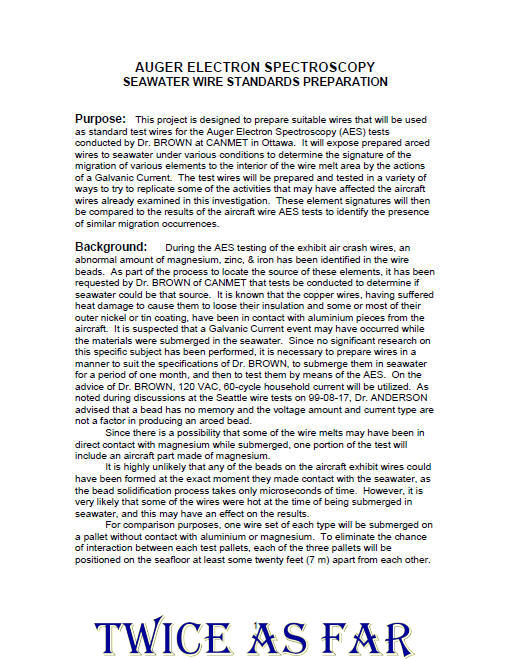
AUGER ELECTRON SPECTROSCOPY
- THE EQUIPMENT -
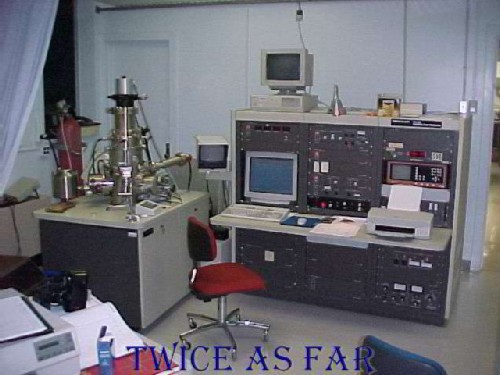
This photo shows the AES (Auger Electron Spectroscopy) unit at CANMET, the Canada Centre for Mineral and Energy Technology of Natural Resources Canada, located at that time in Ottawa, Ontario. Dr. James Brown was the Senior Research Scientist at CANMET, and he operated the AES equipment with his assistant, Larry Galbraith. In 1999, the AES process had already been utilized in the mining industry and in the nuclear energy field for more than twenty years. Auger Electron Spectroscopy is a scientific technique in which an electrically conductive material is subjected to a beam of electrons at the atomic level in an extremely high vacuum. The beam excites the molecules that it strikes, and each then emits what is called an AugerElectron. These electrons are directed to sensors where their energy is individually measured to determine the identity of the elements present at that precise position.
This process is the prime tool for determining the Anderson theory which adapts Sieverts' rule to determine if a short-circuited wire either started or was the result of a fire. Sieverts' rule, a long-established law of physics, states that the surface of a molten material absorbs the atmosphere that surrounds it in direct proportion to its temperature and pressure. Dr. Anderson states that the subsurface of the bead formed during the initial short-circuiting event that then initiates the fire contains the normal pre-fire atmosphere in which it formed. In contrast, the subsurface of the short-circuited bead that is caused by the fire captures the smoke and fire residue that surrounds it at the time it is formed.
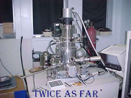
The AES unit shown here is a PHI-600 Scanning AugerMulti-probe. It examines all elements except hydrogen and helium as the electrons for those molecules are first level only. Molecules below these on the periodic table of elements have more than one level of electrons thus allowing one to be released when bombarded. This process is conducted in a vacuum chamber pumped out to 10-10 Tore or 1/10-billionth Tore. One Tore is equal to 1/760 of the earth's normal atmospheric air pressure. The units of depth measurement are Angstroms units. One human hair is about 800,000 angstroms units in diameter, and the depths examined are from 10 angstroms to 5,000 angstroms. It is understood that AES was instrumental in determining the cause of the destruction of the Challenger Space Shuttle moments after lift-off in 1985. It had never been used in an investigation in Canada before this Swissair file even though Dr. Brown is one of the top AES operators in the world.
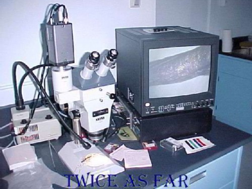
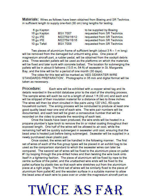
Once the short-circuited wire bead has been washed in an ultrasonic bath of deionised water and then heated to remove the water, it has to be examined under a microscope to determine the best locations for AES probing. The wire on which it is located then has to be trimmed in length to allow it to fit into the examination chamber of the AES unit. This work is done with the aid of this microscope.

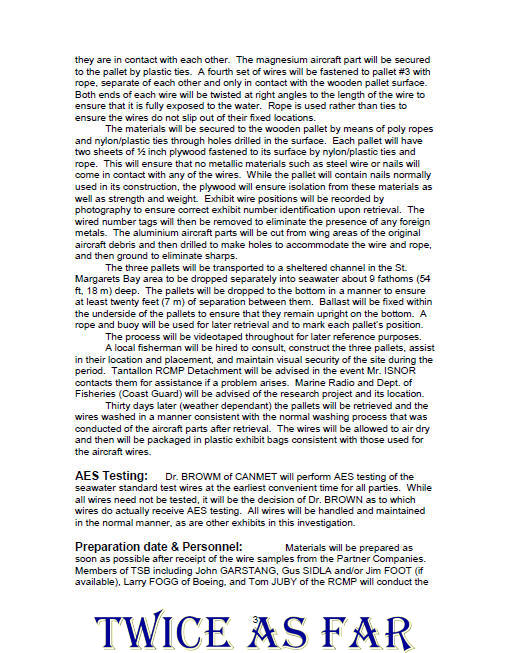
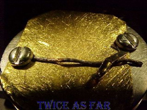
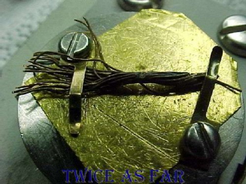
This photo is of the mounting block on which the exhibit wire bead is placed. The sheet of material is gold, and the clamp is copper.
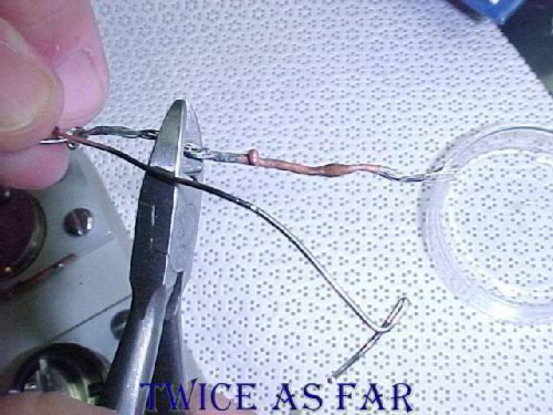
Preparation of the wire for examination includes cutting it to a suitable length to fit inside the chamber. Steel pliers are used, and it is cut so as not to contaminate the bead. The wire is then suspended in a vibrating bath of de-ionized water for fifteen minutes. This particular wire happens to be Exh #1-11175, one of the wires with a high magnesium reading. The AES results are listed below.
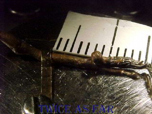
This close-up image shows the wire short-circuit clamped to the mounting dock. The scale shown in the photo is in millimetres. Once mounted, the block is placed in an oven to ensure the evaporation of all the water molecules. While hydrogen cannot be measured by the AES method, oxygen can and if still wet, the molecules of water would flow into the test site to alter the true readings.
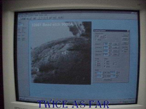
Once in the AES vacuum chamber, the bead can be viewed and positioned in the optimum location for examination. Pertinent data is included in the screen view. However, once the dock with the bead is in the AES unit, it can only be rotated a certain amount. If the second site happens to be on the opposite side of the bead, then the mounting dock must be removed, and the wire turned, then the whole unit reinstalled. This process was a very time consuming procedure and provided an opportunity to photograph all the wires and beads as object models for the MD-11 Tour program.
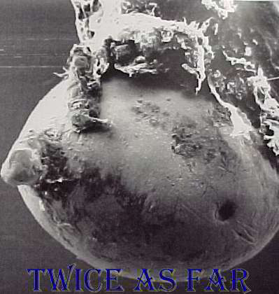
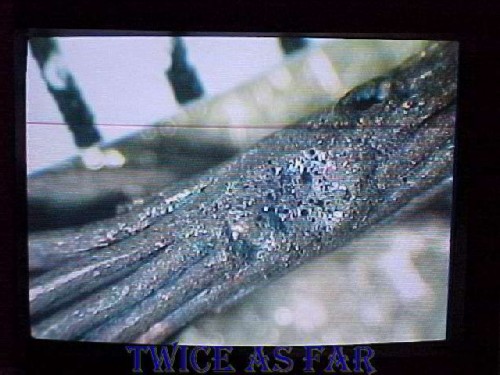
This image is a high magnification photo of one of the short-circuited beads. At the instant of the short circuit the temperatures were hotter than the surface of the sun, so obviously besides melting the copper and anything nearby, material such as plastic insulation was immediately vaporized. However, this photo shows material attached to the beads surface. Therefore it can only be contamination from post short-circuiting activity, something that both the member of the RCMP's Crime Lab and I tried to explain to the TSB member conducting this work. He evaluated the Crime Lab's analysis results by performing comparisons of this contamination material with the standard materials in the aircraft. By that method, he determined the pre-crash positions of the wires. From those results, it was determined which wire was likely the cause of the fire. Those findings would never stand the test of a Court of Law as the TSB member had no qualifications to offer opinion evidence, and no competent examiner would ever verify the results. As for AES, remember that this process examined an area about one-tenth of a micron in size, or less than one ten-thousandth of the width of the actual bead in this photo, the bead being about one millimetre or a thousand microns in diameter.
| ------------ SITE MAP ------------ |
* * * * * * * * * * * *
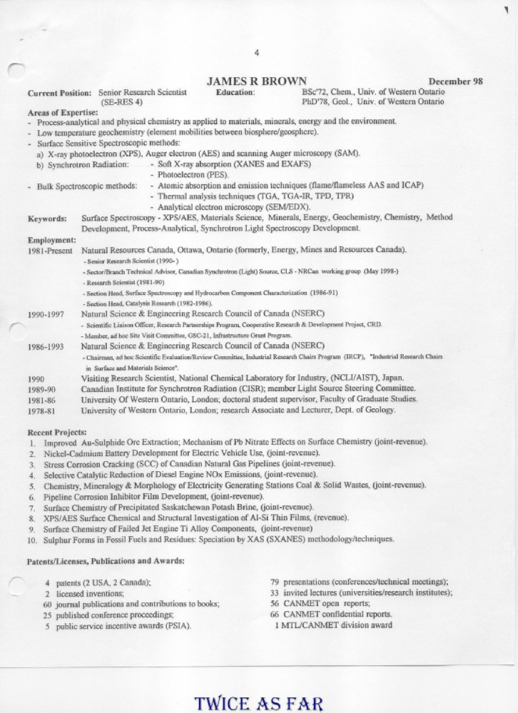
DR. BROWN'S RESUME
The following is Dr. Brown's resume.
Just one page, but what a page!
Before anyone tries to offer a contrary opinion of his findings,
perhaps that person should first consider Dr James Brown's qualifications.
NO ONE IN THE RCMP OR THE TSB HAD ANY SIMILAR QUALIFICATIONS.
| ------------ SITE MAP ------------ |
* * * * * * * * * * * *
AES WIRE PREPARATION AND TESTING VIDEO
AES WIRE PREPARATION & TESTING VIDEO
This video shows the typical preparation of a short-circuited wire for AES testing.
The wires, cut to size, have to be washed in a de-ionized water bath for fifteen minutes.
They are then mounted on the AES stage, covered with a glass cover,
and placed in an oven at just over 100 degrees C to ensure complete drying.
While the hydrogen in any water adhering to the beads surface would not be recorded,
the oxygen in the water molecule would influence the readings.
Once dry, the stage with its exposed wire is inserted into the mounting chamber.
Keep in mind that the AES unit itself cannot be accessed directly.
To open it would contaminate the chamber completely
as it is a vacuum nearly equal to deep space.
| -- AES WIRE PREP VIDEO -- |
| ------------ SITE MAP ------------ |
* * * * * * * * * * * *
AES DATA TABLES
The following tables of figures are a selection of AES data readouts for debris wire short-circuits.
They show high readings of magnesium, aluminium, and iron, and in some cases zinc.
However, these elements are not necessarily all together in the same bead,
If the bead is turned so another location is tested,
the readings may be totally different.
Dr. Brown explained this by stating that smoke is a physical mixture of the various materials being consumed.
Moreover, the air current at the time was likely directional,
Alternatively, the bead itself may have been somewhat protected by other wires.
Indeed, if the readings were identical at all points,
one might wonder about the legitimacy of the findings.
For those who forget their chemistry symbols, the following is supplied:
|
Symbol |
Element |
|
Al |
Aluminium |
|
C |
Carbon |
|
Ca |
Calcium |
|
Cl |
Chlorine |
|
Cu |
Copper |
|
F |
Fluorine |
|
Fe |
Iron |
|
K |
Potassium |
|
Mg |
Magnesium |
|
Mn |
Manganese |
|
N |
Nitrogen |
|
Ni |
Nickel |
|
O |
Oxygen |
|
P |
Phosphorus |
|
Pb |
Lead |
|
S |
Sulphur |
|
Sn |
Tin |
|
Zn |
Zinc |
The exhibit numbers are listed in the last table below to provide the known details of the wire.
Keep in mind that each bead is the short-circuited area of an aircraft debris wire.
Some wires are original aircraft cables, and others are from the IFE (In Flight Entertainment) power feed wires.
For the AES tables,
the symbols across the top are the elements.
On the left is the depth in Angstrom units.
Less than 100A is considered the environmental cap
and it is not considered indicative of the wire bead's environment at the time of its formation.
Each horizontal line contains the percentage of the element heading that column.
The sum of the horizontal line should be 100.
What had caught the interest of Dr. Brown and others is the readings of Mg, Al, Fe, and Zn.
The explanation was offered by some that the magnesium (Mg) came from the aluminium alloy structure of the plane
as it has as much as 4 percent magnesium in the alloy.
However, it can be seen that magnesium in many instances far surpasses the percentage of aluminium,
sometimes by eight times or more just in this first table.
In one table, magnesium is sixteen percent with no aluminium at all.
It was put forward that due to cracks and fissures in the copper bead,
seawater contaminated the wire interiors.
However, two things refute that theory.
First,
seawater contains an abundance of elements,
many of which are not present in these tables.
If seawater had been the source,
AES would have found them,
and they would be listed with their percentage of the total number of molecules present.
Second,
test wires were created by short-circuiting the identical type of aircraft wires
and they were then submerged in sea water for thirty days.
Not one of those wires showed the inclusion of
magnesium, iron, aluminium, zinc, or any other element
that should not have been in the bead.
It was also put forward that there must have been an onboard source for the questioned elements.
Samples of everything available were either provided to Dr. Brown for analysis,
or were tested by various labs to determine their elemental composition.
Nothing contained the elements in question,
and the aircraft's structure could not account for the range of percentages of aluminium and magnesium
that were collected in the AES examinations of the wire beads.
After all this testing,
Dr. Brown provided a source and an explanation.
However, neither the TSB nor RCMP management would hear of it
as the TSB does not conduct criminal investigations
and the RCMP did not wish to take on the file as a multiple homicide investigation.
This file was not to be anything else but a safety investigation.
Exh # 1-11165
(From Exh #1-3700)
Point Scan Results - Site #1, Spot #1 CANMET - 99 SEP 20
|
DEPTH |
Cu1 |
C1 |
O1 |
N1 |
Ni3 |
S1 |
Al2 |
Mg2 |
Mn2 |
Sn1 |
Cl1 |
Ca1 |
K1 |
|
Pre-etch |
15.6 |
38.9 |
23.2 |
1.9 |
1.4 |
1.2 |
6.6 |
8.7 |
0 |
0.3 |
0.5 |
1.7 |
0 |
|
50A |
20.5 |
22.7 |
28.6 |
0.9 |
? |
1.3 |
8.2 |
13.7 |
1.4? |
0.3 |
0.2 |
2.2 |
0 |
|
100A |
22.3 |
20.7 |
27.9 |
0.9 |
2.8 |
1.1 |
7.1 |
14.3 |
0 |
0.3 |
0.2 |
2.2 |
0 |
|
300A |
24.5 |
13.4 |
26.6 |
0.8 |
2.4 |
0.6 |
5.0 |
23.7 |
0 |
0 |
0 |
3.0 |
0 |
|
500A |
23.7 |
10.5 |
25.6 |
0 |
2.1 |
0.5 |
3.9 |
24.9 |
0 |
0 |
0 |
3.0 |
0 |
|
1000A |
25.9 |
10.0 |
26.1 |
0 |
1.8 |
0.4 |
3.8 |
27.4 |
0 |
0 |
0 |
3.8 |
0.8 |
|
2000A |
32.9 |
10.2 |
25.2 |
0 |
3.0 |
0.5 |
3.0 |
19.5 |
0 |
0 |
0.3 |
4.7 |
0.7 |
|
3000A |
35.9 |
9.7 |
33.0 |
0 |
11.0 |
0.7 |
0 |
4.2 |
0 |
1.1 |
0.8 |
2.4 |
1.1 |
|
5000A |
58.3 |
0 |
22.6 |
0 |
5.1 |
0 |
0 |
6.8 |
0 |
0.5 |
0.6 |
5.5 |
0.6 |
Point Scan Results - Site #3, Spot #3 CANMET - 99 SEP 21
|
DEPTH |
Cu1 |
C1 |
O1 |
N1 |
Fe3 |
S1 |
Al2 |
Mg2 |
Pb1 |
Sn1 |
Cl1 |
Ca1 |
K1 |
|
Pre-etch |
21.7 |
26.1 |
21.5 |
1.5 |
0 |
0.5 |
8.8 |
9.4 |
7.8 |
0 |
0 |
1.4 |
0 |
|
50A |
27.1 |
14.0 |
32.2 |
1.0 |
1.2 |
0.5 |
12.1 |
10.9 |
0 |
0 |
0 |
0.3 |
0 |
|
100A |
28.9 |
13.3 |
32.3 |
1.1 |
1.2 |
0.6 |
12.2 |
9.9 |
0 |
0 |
0 |
0.4 |
0 |
|
300A |
26.7 |
11.1 |
33.3 |
0 |
2.0 |
0.6 |
15.0 |
10.5 |
0 |
0 |
0 |
0 |
0 |
|
500A |
23.8 |
9.8 |
35.1 |
0.7 |
1.1 |
0.5 |
14.2 |
14.3 |
0 |
0 |
0 |
0.4 |
0 |
|
1000A |
23.6 |
9.0 |
36.3 |
0.9 |
1.7 |
0.4 |
10.8 |
16.9 |
0 |
0 |
0 |
0.4 |
0 |
|
2000A |
20.2 |
6.7 |
37.6 |
0 |
2.1 |
0.4 |
11.8 |
20.7 |
0 |
0 |
0 |
0.5 |
0 |
|
5000A |
26.6 |
4.0 |
36.4 |
0 |
1.8 |
0.6 |
8.6 |
21.4 |
0 |
0 |
0 |
0.6 |
0 |
|
7000A |
36.9 |
3.7 |
30.8 |
0 |
2.3 |
0 |
8.1 |
16.7 |
0 |
0 |
0 |
0.7 |
0 |
|
10000A |
57.2 |
2.8 |
22.4 |
0 |
0 |
0 |
4.9 |
11.7 |
0 |
0 |
0.3 |
0.6 |
0 |
Point Scan Results - Site #4, designated Spot #4 CANMET - 99 SEP 21
|
DEPTH |
Cu1 |
C1 |
O1 |
N1 |
Fe3 |
S1 |
Al2 |
Mg2 |
Pb1 |
Sn1 |
Cl1 |
Ca1 |
K1 |
|
Pre-etch |
13.6 |
25.0 |
22.6 |
0.8 |
0 |
1.1 |
0 |
15.6 |
0.8 |
0.1 |
0 |
19.2 |
1.1 |
Dr. Brown decided to eliminate C1 from spectrum and revised the printout.
|
DEPTH |
Cu1 |
C1 |
O1 |
N1 |
Fe3 |
S1 |
Al2 |
Mg2 |
Pb1 |
Sn1 |
Cl1 |
Ca1 |
K1 |
|
Pre-etch |
0 |
0 |
30.2 |
1.1 |
0 |
1.5 |
0 |
20.8 |
1.0 |
0 |
0 |
25.7 |
1.4 |
|
500A |
9.1 |
0 |
37.8 |
0 |
0 |
0.5 |
0 |
9.7 |
0 |
0 |
0 |
40.0 |
2.8 |
Exh # 1-11166
(From Exh #1-3788)
Point Scan Results - Site #1, Spot #1 CANMET - 99 SEP 20
|
DEPTH |
Cu1 |
C1 |
O1 |
N1 |
Fe3 |
S1 |
Al2 |
Mg2 |
Pb1 |
Sn1 |
Cl1 |
Ca1 |
F1 |
|
Pre-etch |
6.9 |
80.3 |
7.5 |
1.1 |
0 |
0.4 |
4.5 |
0 |
0 |
0 |
0.2 |
0 |
0 |
|
50A |
15.6 |
56.8 |
9.0 |
1.2 |
0 |
0.6 |
0 |
4.4 |
6.0 |
0.2 |
0.3 |
0 |
0.6 |
|
100A |
33.1 |
46.7 |
12.3 |
1.2 |
0 |
0.6 |
0 |
5.4 |
0 |
0 |
0.4 |
0 |
0 |
|
200A |
30.4 |
48.7 |
11.7 |
1.1 |
0 |
0.7 |
0 |
6.3 |
0 |
0 |
0.3 |
0.4 |
0.4 |
|
400A |
42.9 |
40.8 |
12.3 |
1.3 |
0 |
0.9 |
0 |
0 |
0 |
0.8 |
0.5 |
0.5 |
0 |
|
1000A |
87.7 |
4.9 |
6.3 |
0 |
0 |
0 |
0 |
0 |
0 |
1.2 |
0 |
0 |
0 |
|
1500A |
94.2 |
3.8 |
1.2 |
0 |
0 |
0 |
0 |
0 |
0 |
0.4 |
0.4 |
0 |
0 |
Point Scan Results - Site #2, Spot #2 CANMET - 99 SEP 21
|
DEPTH |
Cu1 |
C1 |
O1 |
N1 |
Zn3 |
S1 |
Al2 |
Mg2 |
P1 |
Sn1 |
Cl1 |
Ca1 |
K1 |
|
Pre-etch |
3.5 |
35.3 |
27.3 |
2.0 |
0 |
0.6 |
12.4 |
17.5 |
0.6 |
0 |
0.3 |
0.5 |
0 |
50A Dr. Brown determined no change – spectra not saved
Sputtered to 500A (depth unknown by Dr. Brown – 1.67 minute total etch)
|
DEPTH |
Cu1 |
C1 |
O1 |
N1 |
Zn3 |
S1 |
Al2 |
Mg2 |
P1 |
Sn1 |
Cl1 |
Ca1 |
K1 |
|
1.67 Min |
5.7 |
14.0 |
32.5 |
1.2 |
0 |
0.4 |
10.3 |
35.3 |
0 |
0 |
0 |
0.6 |
0 |
|
3.34 Min |
7.0 |
8.1 |
34.2 |
0.7 |
0 |
0.3 |
10.2 |
38.7 |
0 |
0 |
0 |
0.6 |
0.3 |
|
5.00 Min |
9.5 |
3.9 |
35.5 |
0 |
0 |
0.3 |
7.5 |
42.8 |
0 |
0 |
0 |
0.4 |
0 |
|
10.00 Min |
20.3 |
1.7 |
30.2 |
0 |
5.4 |
0.4 |
6.8 |
34.7 |
0 |
0.2 |
0 |
0.2 |
0 |
|
15.00 Min |
56.9 |
1.2 |
12.7 |
0 |
11.5 |
0.4 |
3.8 |
12.8 |
0 |
0.4 |
0 |
0.3 |
0 |
|
20.00 Min |
88.7 |
0 |
0.6 |
0 |
0 |
0 |
0 |
4.1 |
0 |
0.4 |
0 |
0 |
0 |
(From Exh #1-3796)
Point Scan Results - Site #1, Spot #1 CANMET - 99 NOV 01
|
DEPTH |
Cu1 |
C1 |
O1 |
N1 |
Fe3 |
S1 |
Al2 |
Mg2 |
Zn1 |
Sn1 |
Cl1 |
Ca1 |
Si1 |
|
Pre-etch |
3.8 |
31.5 |
16.3 |
1.0 |
0 |
0.8 |
24.8 |
21.4 |
0 |
0 |
0.1 |
0.2 |
0 |
|
50A |
4.6 |
16.4 |
19.3 |
1.1 |
0 |
0.6 |
33.4 |
24.5 |
0 |
0 |
0 |
0.2 |
0 |
|
100A |
5.0 |
14.7 |
18.5 |
1.0 |
0 |
0.5 |
36.4 |
23.7 |
0 |
0 |
0 |
0.1 |
0 |
|
300A |
4.8 |
11.4 |
22.4 |
0.8 |
0 |
0.4 |
29.8 |
30.1 |
0 |
0 |
0 |
0.2 |
0 |
|
500A |
4.8 |
3.8 |
28.4 |
0 |
0 |
0.3 |
23.5 |
38.9 |
0 |
0 |
0 |
0.2 |
0 |
|
1000A |
4.7 |
2.9 |
27.8 |
0 |
0 |
0.4 |
21.9 |
40.7 |
1.6 |
0 |
0 |
0 |
0 |
|
2000A |
28.6 |
9.1 |
19.4 |
1.0 |
0 |
0.9 |
16.0 |
24.8 |
0 |
0 |
0 |
0.2 |
0 |
|
2500A |
59.6 |
6.6 |
14.3 |
0.9 |
0 |
0.8 |
0 |
15.2 |
2.2 |
0 |
0 |
0.3 |
0 |
|
3000A |
74.7 |
3.3 |
9.8 |
0.7 |
0 |
0.6 |
0 |
9.4 |
1.5 |
0 |
0 |
0 |
0 |
|
3500A |
85.1 |
2.2 |
7.4 |
0.6 |
0 |
0 |
0 |
4.6 |
0 |
0 |
0 |
0 |
0 |
|
4000A |
94.5 |
0 |
5.5 |
0 |
0 |
0 |
0 |
0 |
0 |
0 |
0 |
0 |
0 |
Point Scan Results - Site #2, Spot #1 CANMET - 99 NOV 01
|
DEPTH |
Cu1 |
C1 |
O1 |
N1 |
Fe2 |
S1 |
Al2 |
Mg2 |
Zn1 |
Sn1 |
Cl1 |
Ca1 |
Si1 |
|
Pre-etch |
5.2 |
77.8 |
9.4 |
5.0 |
0 |
1.7 |
0 |
0 |
0 |
0 |
0 |
1.0 |
0 |
|
50A |
5.2 |
59.8 |
7.2 |
4.0 |
1.4 |
1.4 |
15.0 |
0 |
0 |
0 |
0 |
0.7 |
5.2 |
|
100A |
4.6 |
58.5 |
6.6 |
4.0 |
1.2 |
1.1 |
12.3 |
4.9 |
0 |
0 |
0 |
0.8 |
6.0 |
|
300A |
4.8 |
54.9 |
6.6 |
3.6 |
1.3 |
1.1 |
15.5 |
5.2 |
0 |
0 |
0 |
0.7 |
6.3 |
|
500A |
3.1 |
58.6 |
6.4 |
3.3 |
1.4 |
1.0 |
14.1 |
5.8 |
0 |
0 |
0 |
0.6 |
5.5 |
|
1500A |
9.5 |
48.7 |
9.2 |
3.1 |
1.6 |
1.6 |
12.1 |
7.0 |
0 |
0 |
0 |
1.1 |
0 |
|
3500A |
11.1 |
58.5 |
7.6 |
2.6 |
0.9 |
1.1 |
14.9 |
0 |
0 |
0 |
0 |
0.5 |
2.1 |
|
5000A |
35.2 |
34.0 |
5.2 |
1.8 |
0 |
0.8 |
12.8 |
5.0 |
0 |
0 |
0 |
0.4 |
3.7 |
|
7500A |
88.2 |
10.5 |
1.4 |
0 |
0 |
0 |
0 |
0 |
0 |
0 |
0 |
0 |
0 |
Point Scan Results: Site #3, Spot #1 CANMET - 99 NOV 02
|
DEPTH |
Cu1 |
C1 |
O1 |
N1 |
Fe2 |
S1 |
Al2 |
Mg2 |
Ni3 |
F1 |
Cl1 |
Ca1 |
Si1 |
|
Pre-etch |
10.1 |
68.5 |
6.7 |
1.2 |
0 |
1.6 |
11.1 |
0 |
0 |
0 |
0.7 |
0.2 |
0 |
|
50A |
14.9 |
47.4 |
10.0 |
1.3 |
0 |
3.2 |
17.4 |
4.2 |
0 |
0 |
0.4 |
0.3 |
1.1 |
|
100A |
15.5 |
43.9 |
10.4 |
1.2 |
0 |
3.1 |
19.4 |
4.4 |
0 |
0 |
0.3 |
0.4 |
1.5 |
|
200A |
17.8 |
39.1 |
10.9 |
1.1 |
0 |
3.1 |
19.5 |
5.9 |
0 |
0.4 |
0.2 |
0.4 |
1.5 |
|
500A |
23.8 |
29.5 |
11.9 |
1.1 |
0 |
2.8 |
16.0 |
7.7 |
4.8 |
0.3 |
0.2 |
0.5 |
1.5 |
|
1000A |
34.5 |
19.3 |
11.0 |
0.7 |
0 |
2.0 |
15.2 |
8.7 |
5.7 |
0 |
0.3 |
0.7 |
1.9 |
|
1500A |
49.0 |
10.8 |
10.8 |
0.6 |
0 |
1.2 |
17.7 |
9.2 |
0 |
0 |
0.2 |
0.4 |
0 |
|
2000A |
60.9 |
8.1 |
11.2 |
0.5 |
0 |
0.7 |
10.6 |
7.8 |
0 |
0 |
0 |
0.2 |
0 |
|
2500A |
63.6 |
6.3 |
10.0 |
0.5 |
0 |
0 |
10.8 |
8.5 |
0 |
0 |
0 |
0.3 |
0 |
|
3000A |
64.7 |
5.9 |
9.4 |
0 |
0 |
0 |
12.5 |
7.1 |
0 |
0 |
0 |
0.3 |
0 |
|
3500A |
68.5 |
6.2 |
9.0 |
0 |
0 |
0 |
7.8 |
8.1 |
0 |
0 |
0 |
0.4 |
0 |
|
4000A |
74.2 |
7.3 |
9.0 |
0 |
0 |
0 |
0 |
8.9 |
0 |
0 |
0 |
0.6 |
0 |
|
4500A |
68.4 |
6.4 |
7.9 |
0 |
0 |
0 |
9.7 |
7.4 |
0 |
0 |
0 |
0.3 |
0 |
|
5000A |
70.8 |
6.4 |
7.9 |
0 |
0 |
0 |
7.5 |
7.1 |
0 |
0 |
0 |
0.5 |
0 |
|
5500A |
78.8 |
7.5 |
7.5 |
0 |
0 |
0 |
0 |
5.8 |
0 |
0 |
0 |
0.4 |
0 |
|
6500A |
85.9 |
8.6 |
5.5 |
0 |
0 |
0 |
0 |
0 |
0 |
0 |
0 |
0 |
0 |
Point Scan Results - Site #4, Spot #1 CANMET - 99 NOV 02
|
DEPTH |
Cu1 |
C1 |
O1 |
N1 |
Fe2 |
S1 |
Al2 |
Mg2 |
P1 |
Zn1 |
Cl1 |
Ca1 |
Si1 |
|
Pre-etch |
1.4 |
66.2 |
10.2 |
0.6 |
0 |
0.5 |
11.4 |
8.7 |
0 |
0 |
0 |
0.9 |
0 |
|
50A |
2.5 |
54.7 |
12.1 |
0.9 |
0.8 |
0.6 |
16.8 |
8.3 |
0.3 |
0 |
0 |
1.3 |
1.7 |
|
100A |
3.1 |
51.7 |
12.4 |
0.9 |
1.0 |
0.6 |
15.5 |
9.6 |
0.3 |
1.2 |
0 |
1.4 |
2.3 |
|
200A |
3.1 |
47.6 |
12.4 |
0.8 |
1.1 |
0.7 |
16.8 |
13.4 |
0.4 |
0 |
0 |
1.5 |
2.3 |
|
250A |
5.1 |
46.5 |
12.7 |
0.7 |
0.9 |
1.0 |
20.9 |
5.5 |
0.3 |
0 |
0 |
4.7 |
1.6 |
|
300A |
6.0 |
58.5 |
10.7 |
1.0 |
0.8 |
0.9 |
14.7 |
0 |
0.3 |
0 |
0 |
3.8 |
3.3 |
|
400A |
4.9 |
52.4 |
11.5 |
0.7 |
1.1 |
1.0 |
14.2 |
6.2 |
0.6 |
0 |
0 |
5.2 |
2.1 |
|
500A |
5.0 |
53.2 |
10.7 |
1.1 |
1.2 |
0.8 |
15.5 |
4.5 |
0.4 |
0 |
0 |
4.9 |
2.7 |
|
700A |
7.9 |
41.2 |
14.2 |
1.0 |
1.0 |
1.5 |
16.7 |
9.3 |
0.4 |
0 |
0 |
4.4 |
2.3 |
|
1000A |
10.3 |
39.9 |
14.6 |
1.0 |
1.3 |
1.5 |
14.6 |
9.0 |
0 |
0 |
0 |
10.3 |
2.5 |
|
1500A |
15.7 |
30.1 |
15.8 |
1.0 |
1.1 |
1.5 |
14.5 |
9.6 |
0 |
0 |
0 |
7.3 |
3.5 |
|
2000A |
18.9 |
23.1 |
15.7 |
0.8 |
0.9 |
1.2 |
15.2 |
16.3 |
0 |
0 |
0 |
4.5 |
1.2 |
|
2500A |
24.9 |
0.2 |
14.2 |
0.9 |
0 |
1.2 |
12.4 |
12.2 |
0 |
1.1 |
0.2 |
4.4 |
4.2 |
|
3000A |
35.6 |
23.3 |
11.9 |
0.7 |
0 |
1.3 |
13.4 |
9.6 |
0 |
0 |
0 |
4.1 |
0 |
|
3500A |
46.1 |
20.1 |
11.0 |
0.5 |
0 |
1.1 |
10.8 |
7.1 |
0 |
0 |
0 |
3.3 |
0 |
|
4000A |
49.6 |
17.2 |
10.1 |
0.6 |
0 |
1.1 |
11.0 |
7.7 |
0 |
0 |
0 |
2.7 |
0 |
|
4500A |
56.5 |
14.4 |
9.4 |
0.5 |
0 |
1.0 |
11.1 |
4.9 |
0 |
0 |
0 |
2.3 |
0 |
|
5000A |
63.9 |
11.2 |
7.9 |
0 |
0 |
0.7 |
9.2 |
5.3 |
0 |
0 |
0 |
1.7 |
0 |
(From Exh #1-3790)
Point Scan Results - Site #1, Spot #1a CANMET - 00 JAN 11
|
DEPTH |
Cu1 |
C1 |
O1 |
N1 |
Fe2 |
S1 |
Al2 |
Mg2 |
Zn1 |
Sn1 |
Cl1 |
Ca1 |
P1 |
|
Pre-etch |
13.7 |
68.7 |
8.4 |
4.6 |
0 |
0 |
0 |
0 |
0 |
0 |
3.7 |
0.9 |
0 |
|
50A |
32.9 |
40.2 |
11.9 |
3.4 |
0 |
0.7 |
0 |
6.6 |
0 |
0 |
2.1 |
1.4 |
0.8 |
|
100A |
36.1 |
37.3 |
11.3 |
2.8 |
0 |
0.8 |
0 |
8.8 |
0 |
0 |
1.4 |
1.6 |
0 |
|
300A |
47.1 |
20.5 |
12.7 |
2.2 |
0 |
0.9 |
0 |
13.6 |
0 |
0 |
0.9 |
2.1 |
0 |
|
500A |
54.8 |
9.8 |
14.6 |
1.1 |
0 |
0.8 |
0 |
16.2 |
0 |
0 |
0.8 |
1.8 |
0 |
|
800A |
63.2 |
4.7 |
18.0 |
0 |
0 |
0 |
0 |
12.0 |
0 |
0 |
0.8 |
1.3 |
0 |
|
1000A |
68.6 |
2.8 |
17.7 |
0 |
0 |
0 |
0 |
9.4 |
0 |
0 |
0.8 |
0.7 |
0 |
|
1500A |
74.0 |
2.6 |
16.8 |
0 |
0 |
0 |
0 |
5.2 |
0 |
0 |
0.8 |
0.5 |
0 |
|
2000A |
84.7 |
2.2 |
12.5 |
0 |
0 |
0 |
0 |
0 |
0 |
0 |
0.5 |
0 |
0 |
|
3000A |
94.0 |
3.0 |
3.0 |
0 |
0 |
0 |
0 |
0 |
0 |
0 |
0 |
0 |
0 |
Exh #1-12652
(From Exhibit 1-3790)
Point Scan Results - Site #2, Spot #1b CANMET - 00 JAN 12
|
DEPTH |
Cu1 |
C1 |
O1 |
N1 |
Fe2 |
S1 |
Al2 |
Mg2 |
Zn1 |
Sn1 |
Cl1 |
Ca1 |
P1 |
|
Pre-etch |
19.7 |
58.6 |
10.8 |
2.0 |
0 |
1.0 |
0 |
6.8 |
0 |
0 |
0.6 |
0.5 |
0 |
|
3000A |
84.0 |
6.1 |
9.9 |
0 |
0 |
0 |
0 |
0 |
0 |
0 |
0 |
0 |
0 |
Point Scan Results - Site #1, Spot #1a CANMET - 00 JAN 12
|
DEPTH |
Cu1 |
C1 |
O1 |
N1 |
Fe2 |
S1 |
Al2 |
Mg2 |
Zn1 |
Sn1 |
Cl1 |
Ca1 |
P1 |
|
Pre-etch |
5.1 |
84.9 |
4.7 |
1.3 |
0 |
0.5 |
0 |
0 |
0 |
0 |
1.3 |
2.1 |
0 |
|
50A |
12.9 |
69.1 |
8.8 |
1.9 |
0 |
1.6 |
0 |
0 |
0 |
0 |
3.6 |
2.1 |
0 |
|
100A |
15.8 |
64.8 |
10.0 |
1.6 |
0 |
2.1 |
0 |
0 |
0 |
0 |
2.7 |
2.9 |
0 |
|
200A |
19.4 |
52.9 |
11.5 |
1.5 |
0 |
2.3 |
0 |
7.1 |
0 |
0 |
2.2 |
3.1 |
0 |
|
500A |
29.8 |
31.5 |
15.5 |
1.7 |
0 |
2.8 |
0 |
13.9 |
0 |
0 |
1.5 |
3.3 |
0 |
|
1000A |
36.7 |
18.0 |
19.8 |
1.8 |
0 |
2.4 |
0 |
17.1 |
0 |
0 |
1.0 |
3.1 |
0 |
|
1500A |
43.8 |
11.3 |
20.9 |
1.5 |
0 |
1.8 |
0 |
17.4 |
0 |
0 |
0.6 |
2.7 |
0 |
|
2000A |
50.5 |
8.2 |
21.3 |
0 |
0 |
1.6 |
0 |
15.5 |
0 |
0 |
0.5 |
2.2 |
0 |
|
2500A |
57.6 |
7.4 |
20.5 |
0 |
0 |
1.4 |
0 |
10.7 |
0 |
0 |
0.5 |
1.8 |
0 |
|
3000A |
60.0 |
6.6 |
18.9 |
0 |
0 |
1.2 |
0 |
11.1 |
0 |
0 |
0.5 |
1.5 |
0 |
|
4000A |
85.2 |
3.1 |
11.6 |
0 |
0 |
0 |
0 |
0 |
0 |
0 |
0 |
0 |
0 |
Exh #1-12668
(From Exh #1-3792)
Point Scan Results - Spot #1 CANMET – 00 JAN 21
|
DEPTH |
Cu1 |
C1 |
O1 |
N1 |
F1 |
S1 |
Al2 |
Mg2 |
Zn1 |
Sn1 |
Cl1 |
Ca1 |
K1 |
|
Pre-etch |
26.7 |
37.7 |
12.6 |
0 |
0.7 |
1.3 |
0 |
9.5 |
3.5 |
0.4 |
3.5 |
4.1 |
0 |
|
50A |
22.9 |
18.1 |
19.7 |
0 |
0.4 |
2.7 |
0 |
20.0 |
3.6 |
0.5 |
0.7 |
10.1 |
1.4 |
|
100A |
43.6 |
0 |
20.5 |
0 |
0 |
2.1 |
0 |
15.9 |
1.5 |
0.7 |
0.5 |
13.8 |
1.2 |
|
200A |
53.2 |
0 |
18.4 |
0 |
0 |
1.3 |
0 |
10.7 |
0 |
1.3 |
0.3 |
14.9 |
0 |
|
500A |
59.1 |
0 |
15.4 |
0 |
0 |
0.8 |
0 |
8.2 |
0 |
1.7 |
0.3 |
14.5 |
0 |
|
1000A |
74.7 |
0 |
11.3 |
0 |
0 |
0 |
0 |
4.9 |
0 |
1.5 |
0 |
7.6 |
0 |
|
1500A |
88.0 |
3.6 |
5.6 |
0 |
0 |
0 |
0 |
0 |
0 |
1.4 |
0 |
1.3 |
0 |
|
2000A |
90.7 |
5.0 |
2.2 |
0 |
0 |
0 |
0 |
0 |
0 |
1.2 |
0 |
0.9 |
0 |
The following table provides the known details for each of the tested exhibit wires.
AIRCRAFT ARCED EXHIBIT TABLE
|
AES EXHIBIT # |
ORIGINAL EXH # |
CIRCUIT/WIRE # /GAUGE/LENGTH RECOVERED |
COPPER PLATING/INSULATION TYPE/SPECIFICATION |
KNOWN LOCATION IN AIRCRAFT |
|
1-11165 |
1-3700 |
Unknown/ Unknown/ #20 AWG/ 4 inches |
Nickel Plating/ Insulation missing suspected Kapton |
Unknown |
|
1-11166 |
1-3788 |
Unknown/ Unknown/ #16 AWG/12 inches |
Tin Coated/ Unknown/ Unknown |
Unknown |
|
1-11175 |
1-3796 |
Unknown/ unknown/ #16 AWG/10 inches |
Nickel Plating/ Insulation missing suspected Kapton |
Unknown |
|
1-12651 1-12652 |
1-3790 |
IFE Power Feed/ Power Supply unknown/ #12 AWG/40 inches |
Tin Plating/ Modified ETFE/ MIL-W22759/16 |
Unknown |
|
1-12668 |
1-3792 |
IFE Power Feed/ Power Supply unknown/ #12 AWG/40 inches |
Tin Plating/ Modified ETFE/ MIL-W22759/16 |
Unknown |
| ------------ SITE MAP ------------ |
* * * * * * * * * * * *
AES WIRE PREPARATION FOR THE IFEN WIRES
AES WIRE PREPARATION FOR THE IFEN WIRES
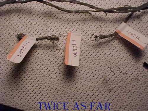
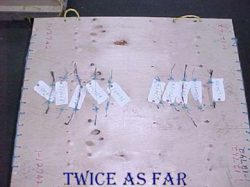
During Auger Electron Spectroscopy (AES) testing, several beads from some of the short-circuited IFEN (entertainment system) wires were examined. These wires had a TEFZEL insulation covering and not the KAPTON coating. Exhibit #1-3793 was a piece of triple strand wire without any insulation but with several short-circuits, two of which were along the same portion of the wire. This photo shows the tags for those short-circuited areas with exhibit 1-12670 already having been removed. It turned out to be unsuitable for testing, but the short circuits on each side of it were suitable. Because the short-circuits at this position had fused all the strands of the wire, their removal for examination would cause the loss of wire integrity. So a steel wire was fastened to the IFEN wire at a sufficient distance to allow the removal of those sections while still maintaining its orientation and length.
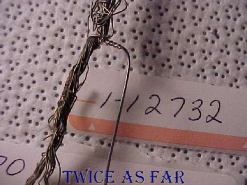
This image is a closer view showing the short-circuit designated exhibit #1-12732 that was on the wire exhibit #1-3793. The bridging steel wire has been fastened in place.
The short circuit area has now been cut from the main strand and is to be processed by washing and drying before being placed in the AES chamber.
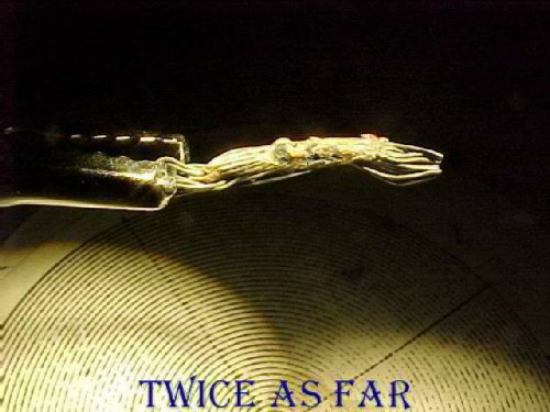
This image is the microscope's viewing screen. It
allowed Dr. Brown to select a
suitable area for the AES processing. The wire, once in the vacuum, can
only be adjusted slightly, so it must be correctly orientated before insertion
into the chamber.
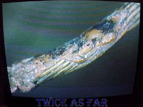
Once in the AES vacuum chamber, it can be analysed to determine the near-surface elements that are present.
The following is a table that provides the examined depths on the left with the name of the elements across the top.
The list of numbers represent the percentages of each element by its number of atoms, not by its weight.
The list of element symbols and element names is below the table.
Remember that anything less than 100 A is still in the environmental cap and subject to surface contamination and handling.
Also remember that the aluminium alloy in the aircraft that makes up the skin and structure is about 3 percent magnesium
and possibly as high as 5 or 6 percent magnesium at the surface.
Here it can be seen that the amount of magnesium below 200 A exceeds the amount of aluminium, sometimes nearly 2:1.
At 3000 A, aluminium runs out, and magnesium remains at 14 and then 10 percent.
Exh #1-12732
(From Exh #1-3793)
Point Scan Results - Spot #1 CANMET - 00 JAN 21
|
DEPTH |
Cu1 |
C1 |
O1 |
N1 |
F1 |
S1 |
Al2 |
Mg2 |
Zn1 |
Sn1 |
Cl1 |
Ca1 |
Si1 |
|
Pre-etch |
6.7 |
79.4 |
10.9 |
1.4 |
0 |
0.7 |
0 |
0 |
0 |
0 |
0.9 |
0 |
0 |
|
50A |
7.6 |
53.7 |
13.1 |
1.4 |
0 |
0.6 |
17.3 |
5.1 |
0 |
0 |
0.6 |
0.6 |
0 |
|
100A |
9.3 |
53.5 |
15.5 |
1.1 |
0 |
0.7 |
11.9 |
6.5 |
0 |
0 |
0.5 |
0.9 |
0 |
|
200A |
10.2 |
43.8 |
16.4 |
1.0 |
0 |
0.7 |
17.5 |
9.0 |
0 |
0 |
0.4 |
0.9 |
0 |
|
500A |
13.3 |
33.2 |
19.8 |
1.2 |
0 |
0.7 |
9.7 |
20.2 |
0 |
0 |
0.5 |
1.3 |
0 |
|
1000A |
13.6 |
26.4 |
21.0 |
1.2 |
0 |
0.6 |
14.1 |
21.1 |
0 |
0 |
0.5 |
1.4 |
0 |
|
1500A |
15.8 |
25.9 |
22.3 |
1.1 |
0 |
0.6 |
12.6 |
19.8 |
0 |
0 |
0.5 |
1.5 |
0 |
|
2000A |
17.6 |
28.0 |
21.5 |
1.2 |
0 |
0.5 |
10.2 |
18.8 |
0 |
0 |
0.5 |
1.7 |
0 |
|
2500A |
19.5 |
30.7 |
19.1 |
1.0 |
0 |
0.6 |
9.6 |
16.9 |
0 |
0 |
0.8 |
1.8 |
0 |
|
3000A |
12.7 |
48.4 |
15.3 |
2.1 |
0 |
0.6 |
0 |
14.1 |
2.4 |
0 |
0.4 |
4.1 |
0 |
|
3500A |
20.5 |
46.6 |
13.9 |
2.0 |
0 |
0.6 |
0 |
10.8 |
0 |
0.2 |
0.5 |
4.8 |
0 |
|
4000A |
33.4 |
37.3 |
14.6 |
2.0 |
0 |
0.8 |
0 |
6.3 |
0 |
0 |
0.5 |
5.3 |
0 |
|
4500A |
65.1 |
14.5 |
15.0 |
0 |
0 |
0 |
0 |
0 |
0 |
0.3 |
0.4 |
4.8 |
0 |
|
5500A |
83.7 |
4.9 |
10.2 |
0 |
0 |
0 |
0 |
0 |
0 |
0 |
0 |
1.2 |
0 |
|
6500A |
90.1 |
3.4 |
6.5 |
0 |
0 |
0 |
0 |
0 |
0 |
0 |
0 |
0 |
0 |
|
AES EXHIBIT # |
ORIGINAL EXH # |
CIRCUIT/WIRE # /GAUGE/LENGTH RECOVERED |
COPPER PLATING/INSULATION TYPE/SPECIFICATION |
KNOWN LOCATION IN AIRCRAFT |
|
1-12732 |
1-3793 |
IFE Power Feed/ Power Supply unknown/ #12 AWG/40 inches |
Tin Plating/ Modified ETFE/ MIL-W22759/16 |
Unknown |
| ------------ SITE MAP ------------ |
* * * * * * * * * * * *
AES REPORT TO LATHEM - 99 SEP 29
AES REPORT TO LATHEM - 99 SEP 22
This memo was submitted to Gorman and Lathem
with a copy to Karl
Christiansen
on 1999
September 29.
It was an attempt not
to overreact
while making sure that
they understood the implications of the elements.
As can be seen,
I did not
fully understand the complete problem
because aluminium as one of the
suspicious elements was not mentioned.
Chief Superintendent
Duncan and I discussed this memo on the phone
and the result was that I was to monitor all testing procedures.
| ------------ SITE MAP ------------ |
* * * * * * * * * * * *
AES REPORT TO LATHEM - 99 NOV 24
AES REPORT TO LATHEM - 99 NOV 24
This memo was submitted to Gorman and Lathem on 1999 November 24
as a report for the AES process up until that date.
After the previous memo of the 22nd of September,
the 'folly and reckless' meeting with Lathem had occurred on October 12th, 1999.
So this was an effort to reinforce that first memo after having undertaken the second set of AES testing.
Problems had arisen with the AES equipment at CANMET that soon after was repaired,
Add to this, both Sidla and Foot of the TSB were attempting to close down the testing.
That could not be allowed for any reason, no matter what the TSB wanted.
Note that several paragraphs of this memo have not been included here
as they pertain to equipment repair details and unrelated events.
I must have done a good job in writing this memo.
Lathem seems to have been able to understand every bit of it
because neither he nor Gorman
ever came to me to discuss any part of it or the details it contained.
After each and every test trip,
a report was submitted to Gorman along with a complete copy of my notes.
Those reports were addressed to Lathem,
and everything was supposed to end up on the file
by way of Purchase and Stothart.
I was never asked to clarify anything about what was explained in those reports.
| ----------- SITE MAP ------------ |
* * * * * * * * * * * *
| BURNING MATERIALS TEMPERATURE CHART | |||
| MATERIAL | IGNITION TEMPERATURE |
MELT TEMPERATURE |
FLAME TEMPERATURE |
| C o / F o | C o / F o | C o / F o | |
| Aluminum Block | 3826 / 6920 | 659 / 1218 | - |
| Magnesiium Block | 3099 / 5610 | 650 / 1202 | - |
| Metallized Mylar | - | - | 1203 / 2200 |
| Aluminum Powder | 760 / 1400 | 659 / 1218 | 3173 - 3273 / 5743 - 5923 |
| Magnesium Ribbon | 473 / 883 | - | 2482 / 5000 |
| Charcoal Fire | 349 / 660 | - | 750 - 1200 / 1382 - 2192 |
| Candle | 650 / 1202 | - | 1100 - 1400 / 2012 - 2552 |
| Gasoline | 400 / 752 | - | 1026 / 1879 |
| Wood | 300 / 572 | - | 1027 / 1881 |
| THE LAST FOUR ITEMS IN THE LIST ARE PROVIDED TO ALLOW A COMPARISON OF MORE COMMONLY KNOWN FIRE MATERIALS |
|||
* * * * * * * * * * * *
THE SEAWATER WIRE TEST PLAN
The following is the seawater wire test plan.
It was prepared to try to solve the question of whether or not the suspicious elements came from seawater.
| ------------ SITE MAP ------------ |
THE SEAWATER WIRE TEST PLAN - PREPARATIONS
THE SEAWATER WIRE TEST PLAN - PREPARATIONS
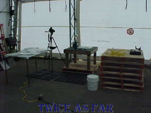
These three photos show the setup that was used to prepare the wires for the seawater wire test. Of course equipment under such circumstances is makeshift as things need to be adapted. A stack of pallets make for a strong table, rubber mats ensure insulation against an accidental electrical shock, a propane torch from the local hardware store provides the heat, and a pail of seawater suffices for the salt water cooling of the wires prepared for that part of the test. Normal household current was utilized by adapting a set of battery jumper cables to an ordinary extension cord.
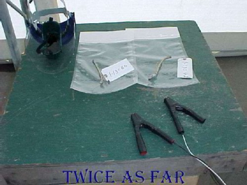
Ordinary household current was used to short the test wires. During the Seattle wire test process, Dr Anderson specifically stated that 'the bead does not retain a memory of the electrical current that caused it'. He was speaking solely of the electrical current and not of the atmosphere that surrounded it at the moment of its melting and solidification. So it made no difference what the voltage or current was at the time of the short circuit.
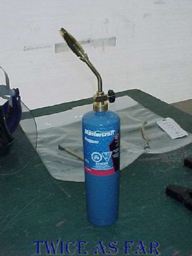
A propane torch supplied sufficient heat to ensure the complete removal of the nickel and tin coating along the wire further from the point of shorting. Additionally, some of the wires in the aircraft had been hot at the moment of the crash. So heating them and immediately immersing them in seawater replicated that effect.
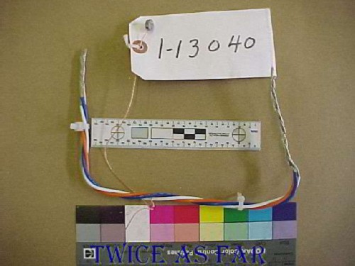
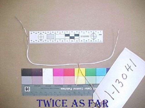
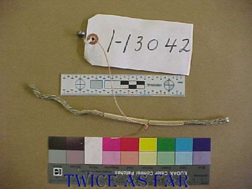
The five photos below show the wires by type that were utilised in the seawater wire short circuit test.
TABLE SHOWING WIRE TYPES
| EXHIBIT # | WIRE TYPE |
| 1-13040 | 12 gu IFE M22759/16/12 |
| 1-13041 |
16 gu IFE M22759/16/16 |
| 1-13042 |
6 gu Kapton |
| 1-13043 |
10 gu TEFZEL BSX 7008 |
| 1-13044 |
16 gu Kapton BSX 7007 |
12 gu IFE M22759/16/12
Used as the power wires for the IFEN system.
16 gu IFE M22759/16/16
6 gu Kapton
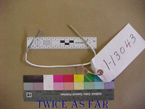
10 gu TEFZEL BSX 7008
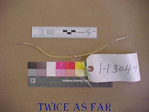
16 gu Kapton BSX 7007
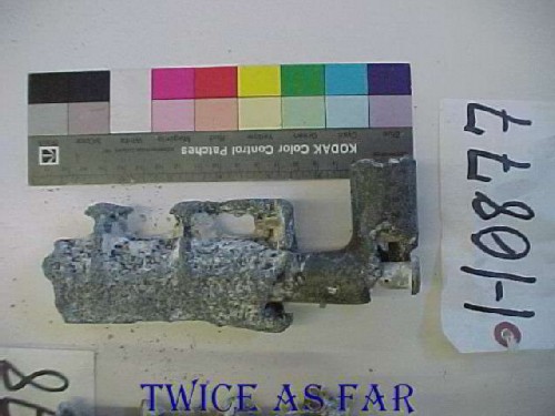
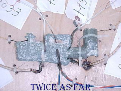
The CBC program 'The Fifth Estate' generated considerable debate about the amount of magnesium that was onboard the aircraft. Boeing had advised that there were only the four rudder pedals and small pieces in the door mechanisms that were pure magnesium. While the aluminium skin and structure pieces were an aluminium - magnesium alloy, the amount of magnesium in the alloy was at best about three to five percent. With readings showing twenty to forty percent magnesium with no aluminium present, obviously, the magnesium source was not from the aircraft structure. This photo shows the rudder pedal that was used for the seawater short circuit wire tests before its attachment to the test pallet. The bonus was that a piece of steel which can be seen at the right end of the unit but left of the 1-1 on the tag was also present as a possible source of iron. Boeing was against conducting this part of the test, but Dr. Brown was confident that seawater and especially a piece of pure magnesium was not the source of the magnesium in the AES readings.
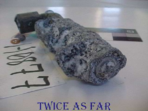
Another view of the same rudder pedal showing that the steel pin carries through the length of the unit.
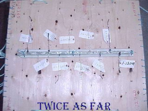
These photos show the pallets that were constructed specifically for the tests. A high-quality standard hardwood pallet was used as the base of all three to which a sheet of 3/4 inch plywood was attached with rope ties as shown in the photos to secure it on the pallet. There was a need to ensure that no foreign metal objects such as pallet nails or screws influenced the readings. The exhibit wires were shorted, cooled, and positioned on each pallet according to the plan with each being secured to the pallet by nylon ties. Of course, each pallet was marked as an exhibit, this one being exhibit #1-12740. As seen, this pallet has the strip of aircraft aluminium secured to the pallet with the shorted wires attached through new holes drilled in the metal.
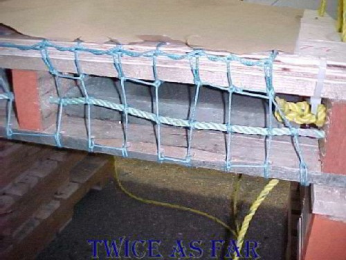
This photo shows the method used to fasten down the covering layer of 3/4 plywood as well as the addition of four cement patio stones as ballast to keep it all on the bottom. Additional nylon ties were used to hold down the sheet of plywood.
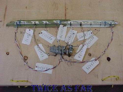
This photo shows exhibit #1-12741, the pallet that had a piece of the aluminium alloy structure and magnesium rudder pedal. The wires were attached through freshly drilled holes in the alloy metal. The pure magnesium rudder pedal was positioned so the short-circuited end of each wire fastened near it to maintain continuous contact.
This photo shows the positioning of the wires against the magnesium rudder pedal to ensure continuous contact.
The third pallet consisted of wires only, each fastened in place with nylon ties.
When the pallets with the attached exhibits were submerged in seawater,
all of the number tags had already been removed.
| ------------ SITE MAP ------------ |
* * * * * * * * * * * *
AES-4 WIRE EXAMINATION & RESULTS
AES-4 WIRE EXAMINATION & RESULTS
During AES-4, the following three debris wires were examined by Dr Brown with the attached results.
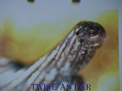
This photo shows exhibit # 1-12736, a short circuit removed from wire exhibit #1-12809, a 24 gauge wire about ten inches long from an unknown location in the aircraft and for an unknown purpose. However, it was a debris cable, had undergone the similar conditions as all the others, and the AES results are listed below.
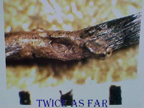
This photo is a closer view of the melt area on the wire. The black bars at the very bottom are from a metric scale ruler indicating millimetres in length. So the overall melt area is about 2 mm in length, and less than 1 mm in overall thickness.
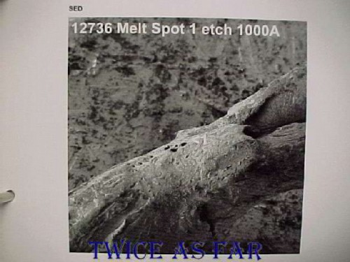
This image was taken by the AES unit itself and shows the melt area with a great depth of field. At about centre of the photo, one can see a printed number '1' on the surface, and this indicates the examination site. The surface may look rough and possibly porous, but keep in mind the scales involved.
1 in = 25.4 mm
1 mm = 1000 microns
1 micron = 10,000 angstroms
1 angstrom = 10-10 meters, 0.0000000001 m, 1/10-billionth of a meter
1 in = 254,000,000 angstroms
1 human hair = approx. 80 microns or 800,000 angstroms in diameter
As can be seen in the tables below, there was no magnesium or aluminium in the bead at all, and very little of anything else but copper and some nickel. It was obviously a nickel-coated wire, thus explaining that source. So as porous as the wire may appear when normally viewed, there was no evidence of any seawater intrusion or other post-crash contamination.
Exh #1-12736
(From Exh #1-12809)
Point Scan Results - Site #1, Spot #1 CANMET – 00-03-01
|
DEPTH |
Cu1 |
C1 |
O1 |
N1 |
Fe2 |
S1 |
Al2 |
Mg2 |
Zn1 |
Ni3 |
Cl1 |
Ca1 |
Si1 |
|
Pre-etch |
33.1 |
49.5 |
9.9 |
1.9 |
0 |
1.5 |
0 |
0 |
1.9 |
<2 |
0.9 |
1.3 |
0 |
|
50A |
84.2 |
6.7 |
7.0 |
0 |
0 |
0.7 |
0 |
0 |
0 |
0 |
0 |
1.4 |
0 |
|
100A |
77.6 |
2.7 |
4.5 |
0 |
0 |
0 |
0 |
0 |
0 |
<14.4 |
0 |
0.8 |
0 |
|
200A |
80.8 |
1.3 |
2.8 |
0 |
0 |
0 |
0 |
0 |
0 |
<15.1 |
0 |
0 |
0 |
|
500A |
80.0 |
2.7 |
1.6 |
0 |
0 |
0 |
0 |
0 |
0 |
<15.7 |
0 |
0 |
0 |
|
1000A |
80.7 |
1.2 |
3.6 |
0 |
0 |
0 |
0 |
0 |
0 |
<14.5 |
0 |
0 |
0 |
Point Scan Results - Site #2, Spot #2 CANMET – 00-03-01
|
DEPTH |
Cu1 |
C1 |
O1 |
N1 |
Fe2 |
S1 |
Al2 |
Mg2 |
Zn1 |
Ni3 |
Cl1 |
Ca1 |
Mn3 |
|
Pre-etch |
25.8 |
50.9 |
12.0 |
0.9 |
0 |
0.5 |
0 |
0 |
0 |
7.3 |
1.1 |
0.3 |
1.2 |
|
50A |
76.8 |
5.9 |
15.6 |
0.6 |
0 |
0 |
0 |
0 |
0 |
0 |
0.7 |
0.4 |
0 |
|
100A |
80.8 |
2.7 |
16.1 |
0 |
0 |
0 |
0 |
0 |
0 |
0 |
0.4 |
0 |
0 |
|
200A |
84.5 |
1.4 |
13.8 |
0 |
0 |
0 |
0 |
0 |
0 |
0 |
0.3 |
0 |
0 |
|
500A |
91.0 |
1.4 |
7.5 |
0 |
0 |
0 |
0 |
0 |
0 |
0 |
0 |
0 |
0 |
|
1000A |
95.0 |
2.2 |
2.8 |
0 |
0 |
0 |
0 |
0 |
0 |
0 |
0 |
0 |
0 |
AIRCRAFT ARCED EXHIBIT TABLE
|
AES EXHIBIT # |
ORIGINAL EXHIBIT # |
CIRCUIT/WIRE # /GAUGE/LENGTH RECOVERED |
COPPER PLATING/INSULATION TYPE/SPECIFICATION |
KNOWN LOCATION IN AIRCRAFT |
|
1-12736 |
1-12809 |
Unknown/ Unknown/ #24AWG/ 10 inches |
Unknown/ Unknown/ Unknown |
Unknown |
|
Symbol |
Element |
|
Al |
Aluminium |
|
C |
Carbon |
|
Ca |
Calcium |
|
Cl |
Chlorine |
|
Cu |
Copper |
|
F |
Fluorine |
|
Fe |
Iron |
|
K |
Potassium |
|
Mg |
Magnesium |
|
Mn |
Manganese |
|
N |
Nitrogen |
|
Ni |
Nickel |
|
O |
Oxygen |
|
P |
Phosphorus |
|
Pb |
Lead |
|
S |
Sulphur |
|
Sn |
Tin |
|
Zn |
Zinc |
This photo shows exhibit # 1-12737, a short-circuit removed from wire exhibit #1-12756, an 18 gauge wire about fifteen and a half inches long with Kapton insulation from an unknown location in the aircraft and for an unknown purpose. Again it was a debris wire, had undergone the similar conditions as all the others, and the AES results are listed below.
This image is a closer view taken of the monitor of the CANMET microscope showing a millimetre scale above the bead. This short-circuited area is less than two millimetres long.
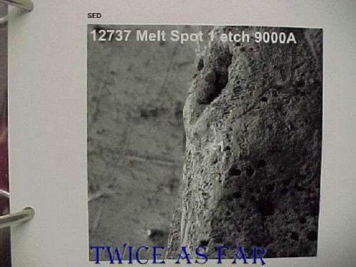
This image is from the AES system and shows the melt area in detail. Again, a numeral '1' is on the image at about the photo's centre to show the location of one of the test sites. The tables below show there was no magnesium, aluminium, iron, or zinc in the bead and very little of anything else but copper and some tin. It was obviously a tin coated wire, thus explaining that source. It is interesting to note that the wire was supposed to have been a nickel plated wire, but instead, it was tin plated. This outer coating has no effect on the performance of the wire as the coating is there merely to add strength and resist high temperatures. The wires are not solid core as are normally found in household wires but instead are made of eighteen strands of copper each coated with tin or nickel and then insulated. This structure allows for more flexibility of the wires without causing their deterioration. It may also be noted that these wires are usually called cables within the industry instead of wires.
Exh #1-12737
(From Exh #1-12756)
Point Scan Results - Spot #1 CANMET – 00-03-01
|
DEPTH |
Cu1 |
C1 |
O1 |
N1 |
Fe2 |
S1 |
Al2 |
Mg2 |
Zn1 |
Sn1 |
Cl1 |
Ca1 |
Si1 |
|
Pre-etch |
48.6 |
29.1 |
17.1 |
1.9 |
0 |
0 |
0 |
0 |
0 |
0.3 |
2.7 |
0.3 |
0 |
|
50A |
65.8 |
6.6 |
25.9 |
0 |
0 |
0 |
0 |
0 |
0 |
0.5 |
1.3 |
0 |
0 |
|
100A |
66.5 |
4.9 |
27.1 |
0 |
0 |
0 |
0 |
0 |
0 |
0.5 |
1.0 |
0 |
0 |
|
200A |
67.6 |
3.8 |
27.2 |
0 |
0 |
0 |
0 |
0 |
0 |
0.6 |
0.8 |
0 |
0 |
|
500A |
69.1 |
3.0 |
26.2 |
0 |
0 |
0 |
0 |
0 |
0 |
0.8 |
0.8 |
0 |
0 |
|
1000A |
70.1 |
2.7 |
24.9 |
0 |
0 |
0 |
0 |
0 |
0 |
1.1 |
1.1 |
0 |
0 |
|
1500A |
67.4 |
2.6 |
25.4 |
0 |
0 |
0 |
0 |
0 |
0 |
3.2 |
1.4 |
0 |
0 |
|
2000A |
60.5 |
2.5 |
28.0 |
0 |
0 |
0 |
0 |
0 |
0 |
7.7 |
0.9 |
0.5 |
0 |
|
2500A |
67.0 |
2.2 |
25.2 |
0 |
0 |
0 |
0 |
0 |
0 |
4.7 |
0.9 |
0 |
0 |
|
3000A |
66.1 |
2.5 |
24.8 |
0 |
0 |
0 |
0 |
0 |
0 |
5.7 |
0.8 |
0 |
0 |
|
5000A |
79.0 |
0 |
14.1 |
0 |
0 |
0 |
0 |
0 |
0 |
6.8 |
0 |
0 |
0 |
|
7000A |
87.2 |
0 |
7.0 |
0 |
0 |
0 |
0 |
0 |
0 |
5.8 |
0 |
0 |
0 |
|
9000A |
89.9 |
0 |
4.7 |
0 |
0 |
0 |
0 |
0 |
0 |
5.4 |
0 |
0 |
0 |
AIRCRAFT ARCED EXHIBIT TABLE
|
AES EXHIBIT # |
ORIGINAL EXHIBIT # |
CIRCUIT/WIRE # /GAUGE/LENGTH RECOVERED |
COPPER PLATING/INSULATION TYPE/SPECIFICATION |
KNOWN LOCATION IN AIRCRAFT |
|
1-12737 |
1-12756 |
Unknown/ Unknown/ #18AWG/ 15.5 inches |
Nickel Plating/ Kapton/Mil-W-81381 |
Unknown |
This photo shows exhibit # 1-12738, a short circuit removed from wire exhibit #1-12755, a 32-inch long nickel plated wire as noted in the table below.
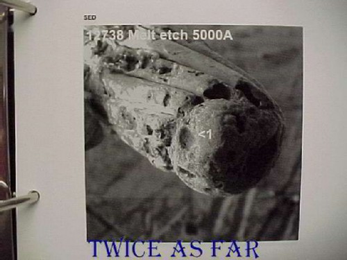
This image is again from the AES system and shows the melt area in detail. Again, a numeral '1' is on the image at about the photo's centre to show the location for one of the test sites. Again there is no magnesium, iron, or aluminium, and only a bit of zinc in the first site. However, this changes somewhat in the second site.
Exh #1-12738
(From Exh #1-12755)
Point Scan Results - Site #1, Spot #1 CANMET – 00-03-02
|
DEPTH |
Cu1 |
C1 |
O1 |
N1 |
K1 |
S1 |
Al2 |
Mg2 |
Zn1 |
Ni3 |
Cl1 |
Ca1 |
Mn1 |
|
Pre-etch |
14.8 |
51.8 |
15.3 |
2.1 |
0 |
2.9 |
0 |
0 |
3.4 |
0 |
8.2 |
1.5 |
0 |
|
50A |
20.9 |
26.0 |
13.5 |
1.1 |
0 |
3.2 |
0 |
4.9 |
0 |
5.6 |
2.5 |
1.0 |
21.4 |
|
100A |
40.4 |
28.3 |
22.7 |
1.0 |
0 |
4.1 |
0 |
0 |
0 |
0 |
2.4 |
1.1 |
0 |
|
200A |
48.0 |
16.6 |
27.0 |
0.7 |
1.7 |
3.0 |
0 |
0 |
0 |
0 |
1.7 |
1.2 |
0 |
|
500A |
54.4 |
8.7 |
28.0 |
0 |
1.8 |
1.9 |
0 |
0 |
2.6 |
0 |
1.9 |
0.7 |
0 |
|
1000A |
67.2 |
0 |
28.3 |
0 |
1.5 |
1.2 |
0 |
0 |
0 |
0 |
1.9 |
0 |
0 |
|
1500A |
66.8 |
0 |
26.6 |
0 |
1.1 |
1.2 |
0 |
0 |
3.2 |
0 |
1.1 |
0 |
0 |
|
2000A |
75.6 |
0 |
22.4 |
0 |
0.9 |
0 |
0 |
0 |
0 |
0 |
1.2 |
0 |
0 |
|
2500A |
77.8 |
0 |
20.1 |
0 |
1.0 |
0 |
0 |
0 |
0 |
0 |
1.1 |
0 |
0 |
|
3000A |
80.0 |
0 |
18.3 |
0 |
0.6 |
0 |
0 |
0 |
0 |
0 |
1.0 |
0 |
0 |
|
5000A |
86.7 |
0 |
13.3 |
0 |
0 |
0 |
0 |
0 |
0 |
0 |
0 |
0 |
0 |
Point Scan Results - Site #2, Spot #1 CANMET – 00-03-02
|
DEPTH |
Cu1 |
C1 |
O1 |
N1 |
Fe1 |
S1 |
Al2 |
Mg2 |
Zn1 |
Ni3 |
Cl1 |
Ca1 |
Si1 |
|
Pre-etch |
15.0 |
59.9 |
15.0 |
2.4 |
4.2 |
2.5 |
0 |
0 |
0 |
0 |
0.7 |
0.3 |
0 |
|
300A |
7.5 |
10.3 |
14.8 |
0 |
7.2 |
1.9 |
11.9 |
5.0 |
0 |
37.8 |
0 |
0.5 |
3.0 |
|
500A |
7.8 |
8.6 |
9.6 |
0 |
3.2 |
1.1 |
9.2 |
2.9 |
0 |
57.1 |
o |
0.5 |
0 |
|
1000A |
5.5 |
4.8 |
5.4 |
0 |
0 |
0.8 |
0 |
0 |
0 |
83.5 |
0 |
0 |
0 |
AIRCRAFT ARCED EXHIBIT TABLE
|
AES EXHIBIT # |
ORIGINAL EXHIBIT # |
CIRCUIT/WIRE # /GAUGE/LENGTH RECOVERED |
COPPER PLATING/INSULATION TYPE/SPECIFICATION |
KNOWN LOCATION IN AIRCRAFT |
|
1-12738 |
1-12755 |
High Intensity Lights/B203-189-22/ 32 inches |
Nickel Plating/ Kapton/ Mil-W-81381 |
Wire run from R5-204 Fwd Overhead Panel to P1-420 Overhead Disconnect Panel |
What is of significance with these three wires
is that even though they underwent the same conditions as the wires that contain the high magnesium,
these wires contain little if any magnesium or aluminium.
It had been argued that the magnesium in the aircraft wire beads
came from the pure magnesium aircraft parts with which those wires allegedly made contact while on the ocean floor.
Those aircraft parts were only four small rudder pedals and tiny pieces of the door locking mechanisms.
For that reason, Dr. Brown had requested the inclusion of a piece of pure magnesium in the seawater wire test.
Even seawater had been argued as the source due to cracks and fissures in the beads.
These wires, formed under the identical conditions,
are clear of any seawater sourced elements.
* * * * * * * * * * * *
AIRCRAFT ALUMINUM ALLOY INGREDIENTS
MAJOR ALLOYING ELEMENTS
BY
MOLECULAR WEIGHT %
REMAINDER IS ALUMINUM
| ALLOY | Cu | Zn | Mg |
| 2024 | 3.8 - 4.9 | 0.25 max | 1.2 - 1.8 |
| 6061 | 0.15 - 0.4 | 0.25 max | 0.8 1.2 |
| 7075 | 1.2 - 2.0 | 5.1 - 6.1 | 2.1 - 2.9 |
These elements are measured in Molecular Weight Percent
while all of the AES reading are in Atomic Percent.
Molecular Weight Percent is measured by utilizing the elements molecular weight
while Atomic Percent utilizes the number of atoms present for each element by percent.
It can be seen that the amounts are somewhat flexible,
but all are within 1% in the case of copper
and much less for the other elements.
The maximum amount of magnesium present is shown as 2.9%
That would be less than 3% in Atomic Percent (AES readings).
The following table provides the approximate Atomic Percent
for the 2024 alloy.
Where there is a variable provided in the above table,
a reading halfway between the two was used.
Remember that the flame front for Metallized Mylar was insufficient to burn the solid alloy
so the alloys could not have been the source.
But even if the alloys could burn, the percentages are too low for them to have been the source.
CONVERTED TO ATOMIC PERCENT
(APPROXIMATE READINGS)
REMAINDER IS ALUMINUM AT 85.430%
| ALLOY | Cu | Zn | Mg |
| 2024 | 11.980 | 0.099 | 1.544 |
* * * * * * * * * * * *
| ----------- NEXT PAGE ------------ |
| ------------- SITE MAP ------------- |
| ------------ TimE line ------------ |
| ----------- HOME PAGE ----------- |
![]()
![]()
![]()
![]()