_svg.png)
TWICE AS FAR
SWISSAIR 111
CRASH INVESTIGATION
![]()
![]()
![]()
- THE INVESTIGATION -
FAA MATERIAL BURN TESTS
CONE CALORIMETER SAMPLE TESTING
CONE CALORIMETER SAMPLE TESTING
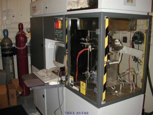
This photo is of Dr. Lyon's cone calorimeter that was the key instrument for the FAA Heat Release Tests. It is designed to take measurements of materials as they burn. It determines the time to ignition, the heat required to ignite, the sample's initial weight, the rate of burn and weight loss, the gasses expelled, and the amount of oxygen required to burn, and among other things, the amount of heat provided during its burning.
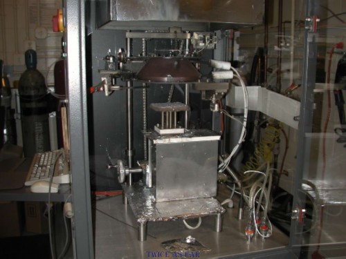
This view shows the operational side of the unit where the sample is mounted. A video is provided to show the unit in operation with a typical sample, and this is the view shown in the video, only with the lights out to show the flame better.
This photo shows the frame unit that holds the sample of material. Samples
were cut to about 5 x 5 inches in size.
This sample is a piece of the elastomeric
duct material or duct joint connectors normally found on one of
the three main air moving ducts.
This photo shows the visual result of the burn test. While not all of it has burnt, the amount of weight loss indicates the amount burnt, and the gasses and heat factors have been recorded. Several samples of the same material are burnt to provide an average.
Another sample of a different material before burning.
It provided some interesting results when subjected to high heat.
This short video shows a typical sample undergoing the heat release test that the cone calorimeter was designed to accomplish.
Time to ignition, amount of heat required for ignition, its weight, the contents of the smoke and the amount of heat given off are all monitored.
The video ends before the sample is finished, but then it is not exactly an exciting spectator's event to watch.
| -- CONE CALORIMETER SAMPLE TESTING VIDEO -- |
| ------------ SITE MAP ------------ |
* * * * * * * * * * * *
FAA-2 PHASE 1 METALIZED MYLAR BURN TEST
FAA-2 PHASE 1 METALIZED MYLAR BURN TEST
The purpose of these burn tests was to attempt,
as nearly as possible,
to replicate some of the events that occurred in the burnt area of the aircraft.
However, all of the equipment in the aircraft could never be accurately placed in such a mock-up.
It was also realized that the amount of flammable material directly associated with the wiring system was minimal,
so that material was not represented.
The Metalized Mylar was the main fuel source.
When Dr. Lyon viewed the frame area and duct placement,
he estimated the amount present to be about 1000 grams or 2.2 pounds.
Given the limited resources available and the desire of the TSB to observe the fire in real time,
there could be no frame enclosure that would restrict oxygen levels
or replicate the minus 60-degree skin temperature caused by high altitude.
However, as nearly as possible, the placement of the main ducts
and their distances in relation to the ceiling were accurately reproduced.
However the accuracy of the type of material used for each burn test was questionable.
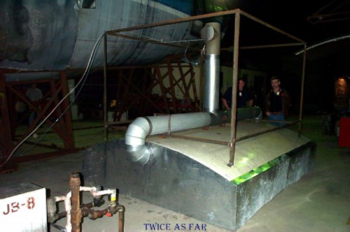
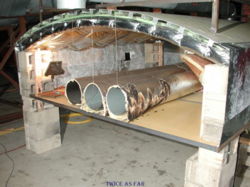
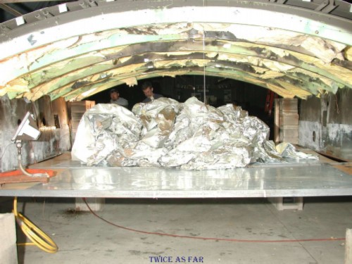
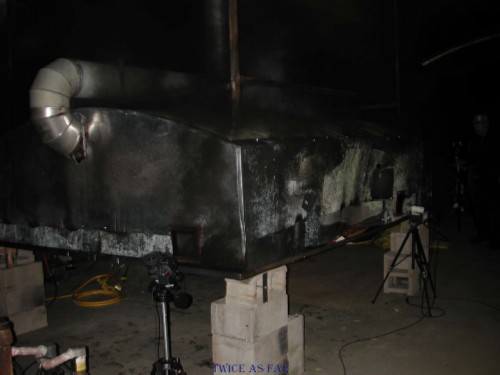
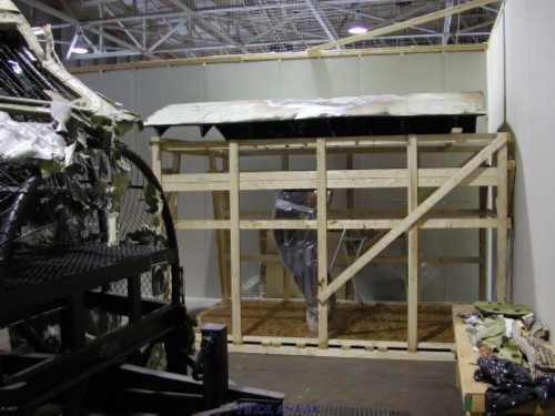
This photo showing the test fuselage was taken on first arriving at the burn centre. The curved ceiling area was a portion of a 747 hull, and the sides were made of tin sheeting. The frame on top supports the smoke chimney. As can be seen, the smoke is intended to exit either end and go out the central stack were sensors monitor its contents. It was immediately realized that the unit had to be raised off the floor for ease of loading the interior with insulation and duct material. Viewing ports with fire proof glass for cameras had been made, so raising it would offer more suitable monitoring. There is a metal floor in the unit to represent the aircraft's ceiling.
This photo gives an idea of the size of this building. The frame
was positioned between the hulls of two
large multi-passenger aircraft. In this
photo the test frame has been
raised to its working position on concrete cinder blocks.
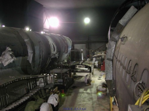
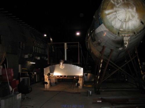
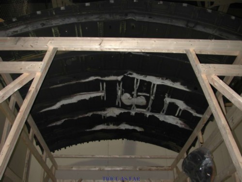
The view inside the building of the two full sized aircraft hulls. The
height of the ceiling was about 50 feet, and the building dimensions were about
100 by 300 feet. The test frame is
between the two aircraft hulls. The smoke
would eventfully fill the building to within eight to nine feet of the
floor during two of the burn tests.
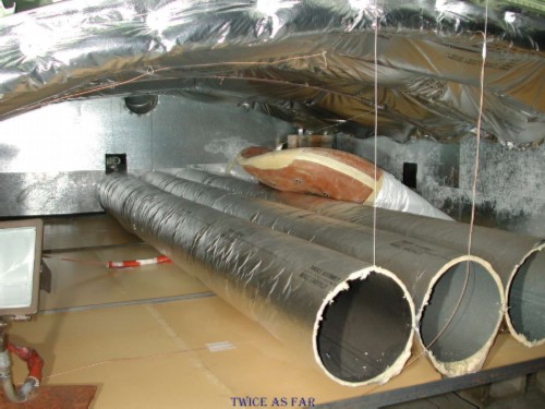
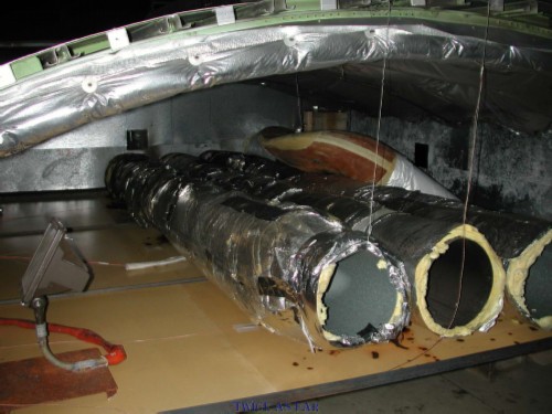
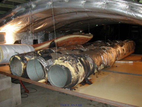
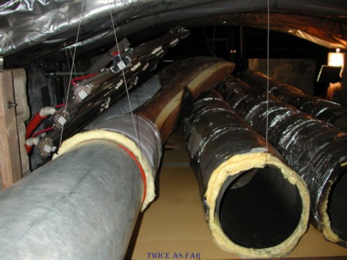
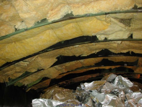
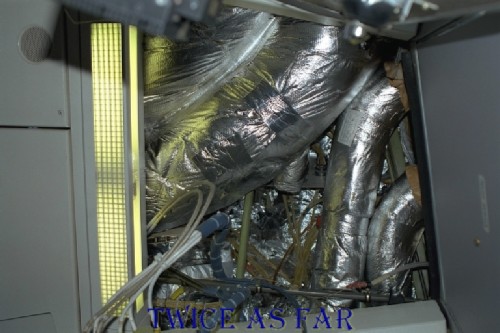
The first test was conducted with the material shown in this photo. The three ducts are wrapped and positioned to represent the three main ducts in the aircraft. The brown coloured fourth duct to the fifth zone is also present in its normal position. The ceiling has insulation blankets consisting of insulation in a Metalized Mylar envelope that is between the longerons or frame stringers, and everything is then covered with larger blankets of Metalized Mylar encasing fibreglass insulation, thus creating the two layers of insulation with actually four layers of Metalized Mylar. The smoke outlet is at the upper edge of the far wall left of centre. Two viewing ports can be seen with a camera visible through the port at the far end of the left duct. To represent the galley area ceiling tiles, the floor of the unit consists of three sheets of tin supported in place by angle iron stringers. The ducts are suspended above the ceiling surface as they would be in the aircraft.
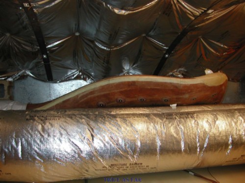
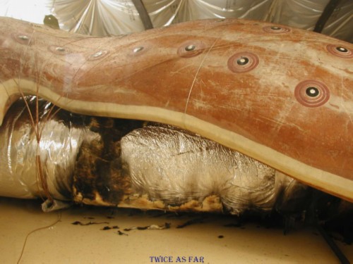
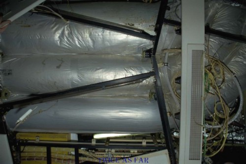
This side view shows the fourth duct, the wrapped main ducts, and the ceiling covering of flammable insulation blankets. Metalized Mylar has a shiny silver reflective finish, while the Metalized Tedlar on the end of the fourth duct has a dull and more greyish finish.
The unit was set alight several times by igniting the bottom of the central ducts, but in less than a minute or so it was realized that this material would not burn. The overhead blankets were Metalized Mylar blankets from the aircraft refits so they would normally burn, but the ducts had been mistakenly wrapped in a Mylar called Orco Film AN-34. This test certainly showed that the material would not sustain a flame front under normal conditions. This material was the same that the Boeing representative advised was wrapping the outside of the Queen Mary Ducts during the Zurich 3 blanket removal trip. By all indications, this material was wrapping the Queen Mary Ducts on Vaud. So it can reasonably be assumed that duct material did not contribute to the fire load unless an accelerant was used to provide a sufficiently hot flame.
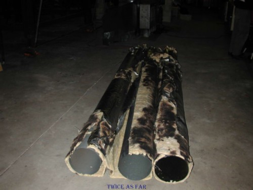
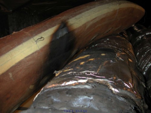
Once the fire was out, what there was of it, the main ducts were removed to show the remaining Mylar material, which was most of it. Where it did burn, it did little if any damage to the fibreglass insulation. It never affected the fourth duct at all or any of the overhead Metalized Mylar.
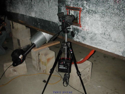
Each side of the frame had a viewing port with a tempered fireproof glass covering. Most of the time it worked well, that is until the frame itself filled with smoke so that nothing could be seen. The unit to the left of the tripod and camera is a blower fitted to a metal duct that then connects to the fourth duct. The idea was to force a moderate amount of air through the fourth duct while it was being heated, as would have been the case on the aircraft.
This test showed that the Orco Film AN-34 material
that had been inadvertently used to wrap the mock ducts
does not burn in a fire that has a normal temperature flame.
Orco Film AN-34 looks similar to the Metalized Mylar that Garstang had wanted to use for this test.
It was an honest mistake that was remedied on the next trip to the FAA burn centre.
However, it raised a couple of points.
The fact that AN-34 does not support a fire under normal conditions was the first.
The second was how much AN-34 was actually in the examined aircraft that we mistook for the flammable type.
John Garstang felt that we had seen none during the trips to Zurich.
AN-34 was found during my resort of the insulation blanket materials that was conducted in J hangar,
and according to the Boeing people present for the Zurich-3 blanket collection,
the plane in Zurich that John did not see had AN-34 on the Queen Mary Ducts as an outer wrap.
That plane was of a similar age as HB-IWF.
AN-34 was present on Vaud, and it seems the fire was hot enough to cause it to burn.
Also note that two other types of similar material were dealt with.
They were Orco Film AN-24 and Orco Film AN-43.
Notes were made of the burn test, and the following is taken from those notes.
At about 1330, with cameras rolling, the three flashes were fired about five seconds apart.
This enabled the timers to be started.
Then Don struck a heat sensor with the flaming lighter.
This sensor was given to him specifically for the purpose so the computer can register a heat spike.
Then, he set alight the duct wrap through the lighting hole.
Three attempts were made at this point, each time with the fire going out after a very short time.
He then went to the forward end to try it several times.
Then he went to the aft end.
As he started the aft burn, I fired the flash once again to sequence the videos even though they had continued to run throughout.
Again, the Metalized Mylar failed to burn beyond a few minutes.
The tapes and cameras were then shut down.
The three ducts were then loosened as they had been wired tightly together as they would have been in an aircraft.
At about 1435, there was a restart of the cameras with the same start sequence of three flashes.
Numerous attempts were made at several locations, but by 1459 hrs, they had all failed and the test was shut down.
Basically, the duct wrap failed to burn with a sufficient amount of heat to cause it to continue to burn either horizontally,
and in some cases, very poorly in a vertical upward manner.
It certainly never came even close to warming the foam duct, and there was absolutely no danger of causing the ceiling to catch fire.
Besides the photos shown above, the test was videotaped by several cameras.
This link shows some of that footage.
It shows the aircraft frame and the failed attempt to burn the Mylar that turned out to be type AN-34.
The left screen shows what would be the left side of the aircraft
while the right screen shows what would be the right side.
Both videos are initially synchronized as closely as possible.
This test proved to be a complete failure
as far as having the material on the ducts burn and cause any melt damage to the frame.
However, it did show that the Metalized Mylar AN-34 would not sustain a normal fire.
One of the questions, therefore, was how much of this material was already in the aircraft,
keeping in mind that it looked identical to the flammable type Metalized Mylar Insulfab 350
that was supposed to be used for the test.
Due to time restraints during the FAA-2 trip
we were unable to undertake a second phase 1 burn test utilizing the correct Metalized Mylar.
It was decided that the test would be conducted as the first test on the next trip.
While other burn tests were scheduled,
this test would be placed ahead of them.
| -- FAA-2 MYLAR BURN TEST VIDEO -- |
| ------------ SITE MAP ------------ |
* * * * * * * * * * * *
EXCERPT FROM FILE NOTES
CONVERSATION WITH DR. LYON
| ------------ SITE MAP ------------ |
* * * * * * * * * * * *
FAA-3 PHASE 1 METALIZED MYLAR BURN TEST
FAA-3 PHASE 1 METALIZED MYLAR BURN TEST
A repeat of the FAA-2 phase 1 burn test was held as the first burn of the FAA-3 trip,
only this time, Metalized Mylar of the type believed to have been on HB-IWF, Insulfab 350, was utilized.
What is disturbing is that during these tests,
the main ducts were wrapped in Metalized Mylar Insulfab 350.
A closer review of the aircraft inspection photos showed that on all but two of the examined aircraft
the same ducts appeared to have been wrapped in the non-flammable Metalized Tedlar
or a material other than the flammable Insulfab 350 Metalized Mylar.
At the time of the inspections, I had noticed but didn't appreciate the difference.
However, only by reviewing the aircraft photos for these pages has that discrepancy now been realized.
The overhead exterior skin insulation was indeed covered in the flammable Metalized Mylar,
but not these main air-handling ducts that ran through the area.
The following is taken from my notes of the FAA burn test.
The fire in the frame was started in the same manner as in the FAA-2 test.
The electronic flash was fired three times at five-second intervals with all the tapes running,
the third being the start point for the counter.
Don then lit the Metalized Mylar from below and it was noted to readily burn.
A large amount of smoke was created and photos were taken of it on roll #004.
It was noted that smoke in the building came down to a level of about nine feet above the floor.
In total, about half of the Metalized Mylar on the three ducts burnt,
but nothing in the ceiling was damaged,
and it appears that no damage was done to the foam duct.
These photos show the setup and the results
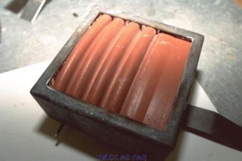
The frame setup was the same as during the first attempt to burn the material, only this time flammable Insulfab 350 Metalized Mylar was applied to the ducts. The ceiling has the same material.
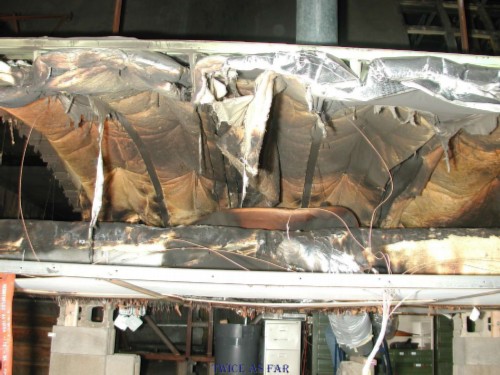
Once the burn was over, this photo shows the extent of the damage in the area of the fourth duct. There was no damage to the top of the duct and little to the material directly below it. The Mylar on the bottom of the main duct is burnt away, but it is noteworthy that the flame front did not continue its natural progression up and along the side of the duct. By this photo, one might think that the Metalized Mylar could indeed pass a legitimate fire test.
This view hows the overall area of the frame floor and how much of the Metalized Mylar remains on the ducts. The ceiling blankets are untouched. Their actual height above the ducts corresponds to that in the MD 11 aircraft at this point in the fuselage. One can see an area of blackening on the fourth duct just left of photo centre.
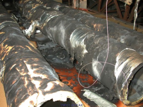
This photo shows the extent of the damage to the fourth duct. While it may give the impression of having been burnt, it is mainly soot from the burning Metalized Mylar that was on the underside of the duct
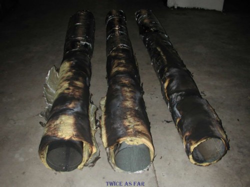
This photo shows the underside of the three ducts and the fact that none of the fibreglass insulation burnt or melted away.
This video link shows the footage taken by the two cameras, synchronized as closely as possible.
At the start, footage from a third overview camera showing the frame and its setup is played in both screens.
The fan noise is the blower for the fourth duct.
For the burn test and the internal frame footage,
the left screen shows the frame looking towards the rear area with the fourth duct on the right side.
The right screen looks forward.
The start and the end portions of the original videos have been edited
to eliminate lead time and the final burn-down time.
Note how slowly the fire advances along the Metalized Mylar,
the same type of material that had covered the skin and frame pieces of HB-IWF.
However, there is every indication that
the ducts had been covered with an even less flammable material - Metalized Tedlar.
In addition,
the burning conditions in the test frame were much more advantageous to allow a complete burn.
That is unless the fire in the aircraft had been assisted by an accelerant.
| -- FAA-3 PHASE 1 MYLAR BURN TEST VIDEO -- |
| ------------ SITE MAP ------------ |
* * * * * * * * * * * *
FAA-3 PHASE 2 FOURTH DUCT BURN TEST
FAA-3 PHASE 2 FOURTH DUCT BURN TEST
Once phase 1 was completed,
preparations were undertaken to conduct the phase 2 burn test
to determine if the fourth duct would burn.
It was important to determine if it added to the fire load in the overhead area.
The theory for the test was that
because the fire had likely started on the right side or the side of the aircraft opposite the fourth duct,
this duct would have been pre-heated by the hot gasses before flames ever reached it.
Therefore a high output heating unit was installed to perform that task.
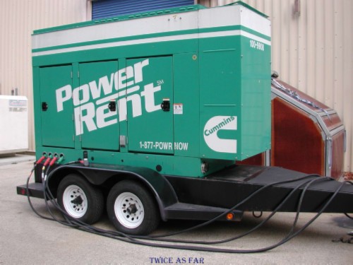
This photo shows the generator that was required to run the heater units that were placed in the frame for the FAA-3 phase-2 burn test. The FAA facility provided 208 V electrical power while the heaters required 240 V power.
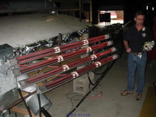
This photo shows the heater units being tested outside of the frame with Don Enns standing beside them. However, he didn't stand there for long before it became too hot. With the correct voltage, the output was tremendous, as can be seen in the video that follows.
The dimensions of the heater panels are as follows:
Length of the three long panels: 85.5 in
Length of the one shorter panel: 73 in
Width of each panel: 3 5/8 in
Overall width of the panels, top to bottom: 20 in
The heat output was not recorded in my notes.
This photo shows the setup with the three main ducts in place and freshly wrapped in the Insulfab 350 Metalized Mylar with the fourth duct to the fifth zone to the left. The ends of it are wrapped in Metalized Tedlar, and the difference is obvious. The electric heaters have been positioned atop the fourth duct. The theory behind it was that the fire likely first occurred on the right side of the ceiling area and it produced sufficient heat to preheat the fourth duct before it caught fire. In this test, the heater units served to preheat the duct.
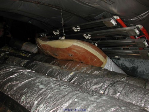
This photo shows the frame setup from the opposite end, or what would be looking towards the rear of the aircraft from ahead of the galley area. The difference here compared to the aircraft was that the three Metalized Mylar covered ducts in the aircraft would have originated in the lower left corner/middle of the photo and then they would immediately turn left to travel towards the rear of the frame.
In this photo it is shown just how much heat can be applied to the fourth duct. Above the duct are the heater units. Below it is the flammable Metalized Mylar that burns with a flame front of about 2200 deg F. However, the question was whether or not the Metalized Mylar was sufficient to provide enough heat to ignite and burn the duct and the Metalized Mylar in the ceiling. Dr. Lyon of the FAA suggested that the overall weight of Metalized Mylar present in this area of the aircraft did not exceed 1 kg or 2.2 lbs. His estimate included the Metalized Mylar on the three main ducts.
Once the heater units were started, they caused the fourth duct's outer finish to catch fire. This fire then involved part of the ceiling material which eventually caused one of the heater units' wires to burn and short-circuit, thus sending sparks across the frame. Before this occurred, the fire on the duct died out even though the heater units were still producing high heat. Some of the sparks from the short circuit landed on the Metalized Mylar of the right-side duct and started a fire at that point.
Once its outer finish was gone, the fire on the fourth duct went out even before the heater units shorted out and were shut down. The resulting Metalized Mylar fire failed to consume the duct, so it seems that the fourth duct did not on its own contribute much to the overall fire load in the test frame or the aircraft.
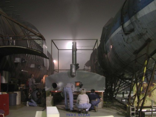
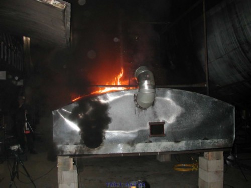
This photo shows the frame about mid-fire, which lasted less than ten minutes. Note the smokestack and the light in the background. The ceiling in the 300 by 100 feet building is about fifty feet high, and the thick smoke came down to within eight feet of the floor. In order to burn all the flammable Metalized Mylar, the material had to be set alight with a lighter at least twice, even after the fourth duct began to burn.
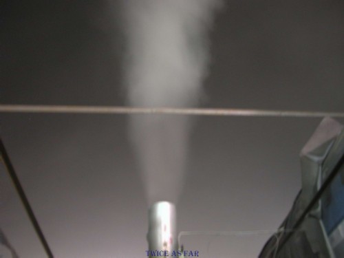
The smoke stack at mid-fire belching smoke. The fire onboard the aircraft would have produced equal amounts of smoke, but spread over a longer period due to limited oxygen and a longer burn time. As well, much of the heat produced would have been lost to the skin of the aircraft which acted as a cold sink.
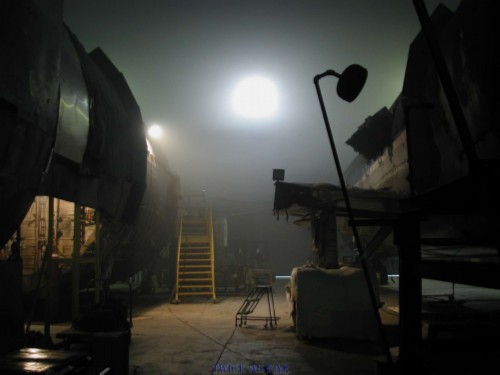
The view inside the building showing the smoke obscuring the lights and the ceiling. The two aircraft hulls provide a sense of scale for the amount of smoke produced and the effect it likely had within HB-IWF.
Once the fire was out, this shows what remained. While the Metalized Mylar around the ducts was nearly all burnt, the fibreglass insulation remained nearly intact. The Metalized Tedlar at the left side of the photo was un-burnt as it would not burn at these temperatures. The fourth duct appeared intact but scorched in the area above photo centre.
This photo better shows the underside of the fourth duct, and while scorched, it remained intact and had not contributed anything of significance to the fire. It can be noted in this photo that exposed Metalized Mylar in the ceiling above the heater units was consumed. This ceiling fire accounted for the burnt wires within the heater units and its short-circuiting during the test.
This photo shows the top surface of the fourth duct that had been exposed to the heater units. When examined, it was found that while the outer coating had burnt, the actual material had not contributed anything of value to the fire.
With the heater unit removed, this photo better shows the duct as well as the ceiling area. What is most significant is that no aluminium melted or showed any signs of degradation due to the fire.
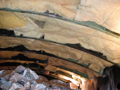
In this photo with the sides of the frame removed to allow access, the Metalized Mylar blankets of the ceiling are still in place, as are the ducts on the floor of the frame. This view of the ceiling area would be from the right side of the aircraft at a point just above the top of the 2.1 or right forward door. The exposed Metalized Mylar of the ceiling blankets was burnt, but the fibreglass and hidden layers of Metalized Mylar were unhurt by the flame.
Another view of the ducts once the fire was out and the smoke had cleared. Not much Metalized Mylar remained on them, but the fibreglass insulation had only been scorched at the surface and remained virtually intact.

The ceiling blankets of Metalized Mylar were another story completely. This photo shows the large covering blankets that remained and the amount of flammable Mylar that failed to burn. What is seen here is the unexposed side of the blankets or the surfaces that were against the smaller inter-frame or intercostal blankets. The ends of the burnt ducts are in the right foreground.
The blankets that were against the skin of the frame were unburnt.
The test fire had at least three things to its advantage versus the fire in the aircraft. The frame was about 65 degrees F instead of minus 60 degrees F. The fire had ample and sufficient oxygen to oxidize the materials rapidly. Then, the materials were dry and without condensation on them to inhibit the flame. However, even with all of this, the fire failed to burn fully all the fire load that was in the frame. What's more, the electric heater applied additional heat to the whole frame including the ceiling area, yet that material failed to be consumed fully. At the end of the fire when the frame itself was examined, no melting of any of the frame's aluminium had occurred.
MY NOTES
The following is taken from my notes for the results of the fire:
Generally, the burn went very well, with the foam duct smoking and then burning while the heaters were activated.
However, as soon as the heaters were turned off, the foam duct quickly extinguished itself.
Just before shutdown, one of the heater units shorted out and sparks were sent flying about the frame.
It appears that one of the sparks landed on an area of the horizontal ducts and caused the Metalized Mylar to catch fire.
The material caught fire and burnt for a period of time,
having been caught on the digital video footage from the left forward corner of the frame.
However, all of the Metalized Mylar in the frame did not burn,
and holes had to be drilled in the walls to allow fire initiation of the ceiling inter-blanket material.
This video link again is from two cameras.
One camera positioned at each end of the test frame.
Each camera's footage, shown one beside the other, is edited to eliminate unnecessary lead times at the beginning of each.
The footage is lengthy, and even though the electric heater ignites the coating on the fourth duct before anything else is set alight,
it quickly burns down, and the Metalized Mylar burns only slowly in certain areas.
The video at the aft end and looking forward is on the right.
The heating elements are positioned above the fourth duct,
and once turned on, they heat the duct to the point that the polymer finish spontaneously ignites.
Then, even though the heaters are still turned on, the fire on the fourth duct dies out.
It can be seen that this fourth duct fire has caused the ceiling to catch fire before the burning of the lower ducts.
Especially in the left screen,
one can see that the fire on the Mylar-covered ducts starts due to the short-circuit sparks from the heater units.
As shown, their was considerable smoke even though there was a normal slow burn of the Mylar material.
While there was considerable heat generated,
much of it was due to the 240 V heater units that initially started the fire.
In fact, the Metalized Mylar on the ducts had to be set alight with a lighter in two different areas to make it to burn.
Regardless, the key point was that there was insufficient heat to melt any of the aluminium of the frame.
| -- FAA-3 PHASE 2 FOAM DUCT BURN TEST VIDEO -- |
| ------------ SITE MAP ------------ |
* * * * * * * * * * * *
FAA-3 METALIZED MYLAR BULK BURN 'FRAUD' TEST
FAA-3 METALIZED MYLAR BULK BURN 'FRAUD' TEST
After the scheduled burns had been completed,
not only was there no molten aluminium,
however, all of the available fire-load material within the frame had not been consumed.
The temperatures within the frame had not been high enough to ignite all the available material.
The tests that had closely replicated a non-criminal fire source had failed to produce the same effects as seen in the crash debris.
Therefore the TSB required a third and unscheduled burn to maintain their assertions of a non-criminal fire.
Thus the 'fraud' burn test was prepared and undertaken.
During the previous FAA-2 trip,
Dr Lyon of the FAA burn test centre had suggested burning about one kilogram or 2.2 pounds
of the Metalized Mylar material in the frame to see what it would do.
That amount was thought to be about equal to the amount of Metalized Mylar in the burnt area of an actual MD-11 aircraft
and it would have been the main source of legitimate fuel for the fire that had downed HB-IWF.
However, Dr. Lyon included in this amount the Metalized Mylar that covered the three main ducts.
He did not seem to know that the TSB had improperly wrapped those ducts in the wrong material.
While the burning of this amount of material had already been done in the phase 1 and phase 2 fires,
Dr. Lyon's suggestion was to pile it loosely in the centre of the frame and see what happens when it all burns at once.
The TSB members had hesitated to do this because of the implications if the burn test failed to melt aluminium.
The TSB then decided to undertake the test.
However, there were additional measures added to the test to ensure the melting of aluminium.
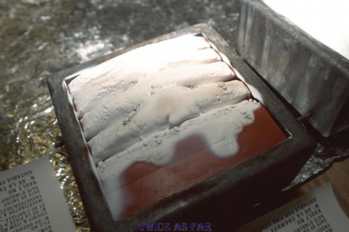
This photo shows the pile of Metalized Mylar bundled loosely on the frame floor that is supposed to represent the ceiling area of the galley of the plane. Also still in the frame is an unknown weight of fresh intercostal or inter-frame fibreglass insulation.
The overhead area of the frame was filled with fresh insulation blankets without the Metalized Mylar in which they had been wrapped. That and more Mylar was now loosely crumpled on the floor of the frame.
This view is of the other side of the frame with the intercostal areas filled with fibreglass.
Once the fire was set alight in the normal fashion, it did not take but a few seconds for it to start an inferno within the frame.
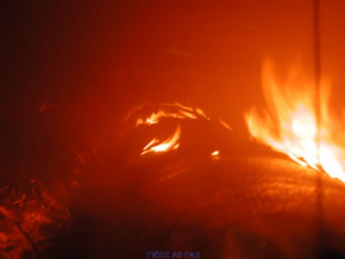
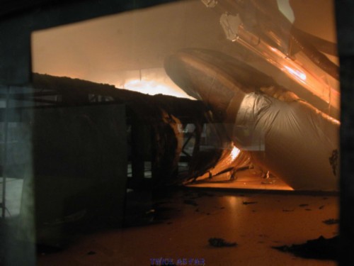
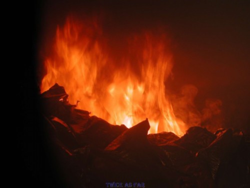
This photo was taken within a minute or so of the fire being set. The windows are dark because there is so much smoke inside the frame that no light can escape. At this point, the cameras are being moved back because the fire has become so intense and violent that the cameras were thought to be in jeopardy.
This photo was taken several minutes into the fire and the roof of the frame had caught fire. The paint on the outside was burning, and it turned out that the frame had cracked due to the heat. The smoke levels in the hangar had dropped down to less than a dozen feet from the floor.
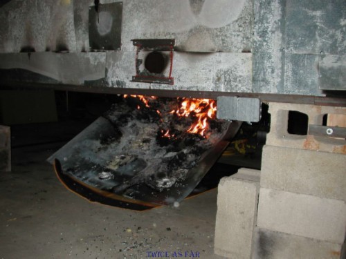
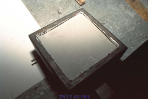
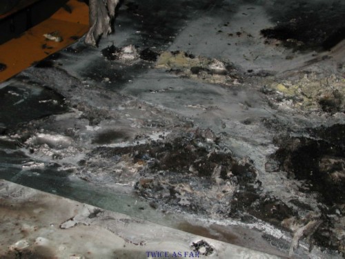
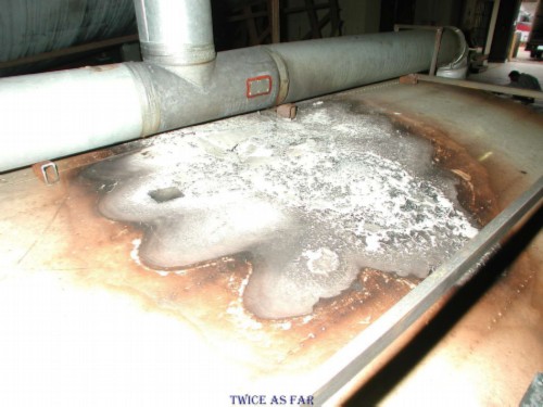
By the end of the fire, one of the floor panels had heated and warped so much that it dropped out of position. However, as can be seen, the flames were nearly out by this time, about five minutes after the fire was started. What can be seen on the panel are areas of molten aluminium from the ceiling frames.
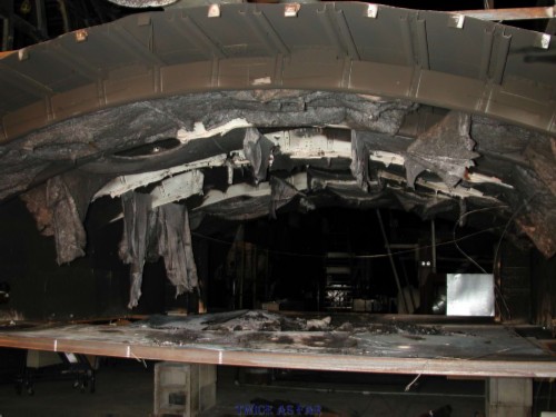
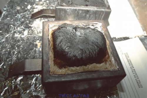
This photo shows the frame after the fire was out and the ends removed. What used to be green was now heavily soot covered. What was now shiny was due to heat discolouration and scouring of the metal by the flames. The fibreglass insulation in places had either been consumed or melted, and the rest was hanging by the wires that were placed to hold the blankets in place.
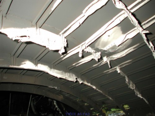
The below centre of this photo shows the ceiling area that had been directly over the bulk of the burning Metalized Mylar. As can be seen, what initially had been complete and intact frame pieces were now either missing or perforated thin wafers due to the heat. This type of damage was extensive in the test frame ceiling.
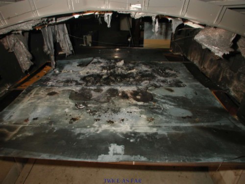
The floor of the frame showed where the alloy for the frame pieces had gone. It was covered with areas of molten aluminium as well as the residue of the fibreglass insulation.
This photo shows some of the extensive amounts of molten aluminium on the metal flooring
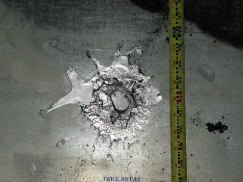
This photo provides a scale for the size of the molten aluminium drops.
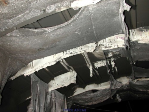
Once the fibreglass was cleaned out of the frame ceiling area, one could better see the damage done to the frame rib units. Several feet of frame rib has melted away at the centre of this photo.
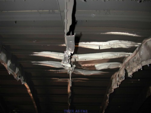
This better shows the frame ribs on each side of the major melt area. Note the perforations in the rib unit at the extreme right of the photo. Also note that the bottom edges of the frame pieces are no longer bent and horizontal to the plane of the floor, but have drooped down and are pointing to the floor.
This photo shows the extent of the burn on the upper surface of the frame's skin.

A closer view of the burn area on the upper surface reveals the crack in the metal hull just to the right and above the photo's centre. The ash-like material is from the burnt paint.
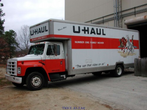
A U-Haul truck was rented to bring the burnt frame back to Canada. John took it first to Ottawa where it was viewed by the TSB file managers and investigators. Then it was shipped by freight to Shearwater where I was told to put it on a display stand beside the reconstruction frame for HB-IWF.
I had offered to drive the truck back to Canada, but John seemed to sense what might happen. Perhaps he thought it would be dumped somewhere along the way as there are many rivers to cross between Atlantic City and the Canadian border. However, a scrap yard somewhere in the New York area would have been my choice. That was where it belonged, and of course doing that would meet with the US anti-pollution laws.
The TSB went to the expense of hauling the frame all the way back to Ottawa and then freighting it to Halifax.
For what purpose?
The TSB had a serious problem of credibility due to the first fire tests.
Those first tests showed that the fire load in the aircraft,
which was represented by the materials placed in the frame for these tests,
was insufficient to melt aluminium.
Indeed, the fire load on the ducts was insufficient to ignite and burn not only all the ceiling material,
it failed to burn all the material on the ducts even with the addition of large, high output heaters.
The final 'fraud' burn was staged to solve the credibility problem.
This test was just that, a fraud!
The fire load in the frame represented
at least six times the amount of material present in the corresponding area of the downed MD-11 aircraft ,
and it burnt in one-quarter of the time.
The burn conditions were such that it had ample amounts of oxygen,
the frame's skin was at least 120 degrees F warmer,
and all the material was dry and crumpled to allow easy and rapid burning with air between the material's layers.
Considering the conversations that I had with both John and Don,
it is my belief that they were both told by their management team to conduct the test
and ensure an outcome that displayed sufficient molten aluminium to eliminate any doubts
that the Metalized Mylar was capable of creating the damage that we had seen in the debris reconstruction frame.
John and Don, being TSB employees, were at the mercy of the demands of their superiors
and they were required to follow those instructions.
What's more, they were not Police Officers so it could be said that they were not bound by the same rules as was I.
As for my role in the tests,
I certainly had no support from my management to interfere with anything that the TSB had planned to do.
Whatever the TSB wanted to do with the materials was covered within their mandate
that stated that they could test to destruction any part of the debris material.
Indeed, none of this material was debris from the crashed plane
so they were simply burning un-associated materials to see what results came of it.
As for putting the results on display,
again I had no control over that.
Indeed, I was tasked with installing the test frame on the wooden stand in the hangar.
As for believing that Gerden controlled this burn,
the following is taken from my file notes for 2001 DEC 17
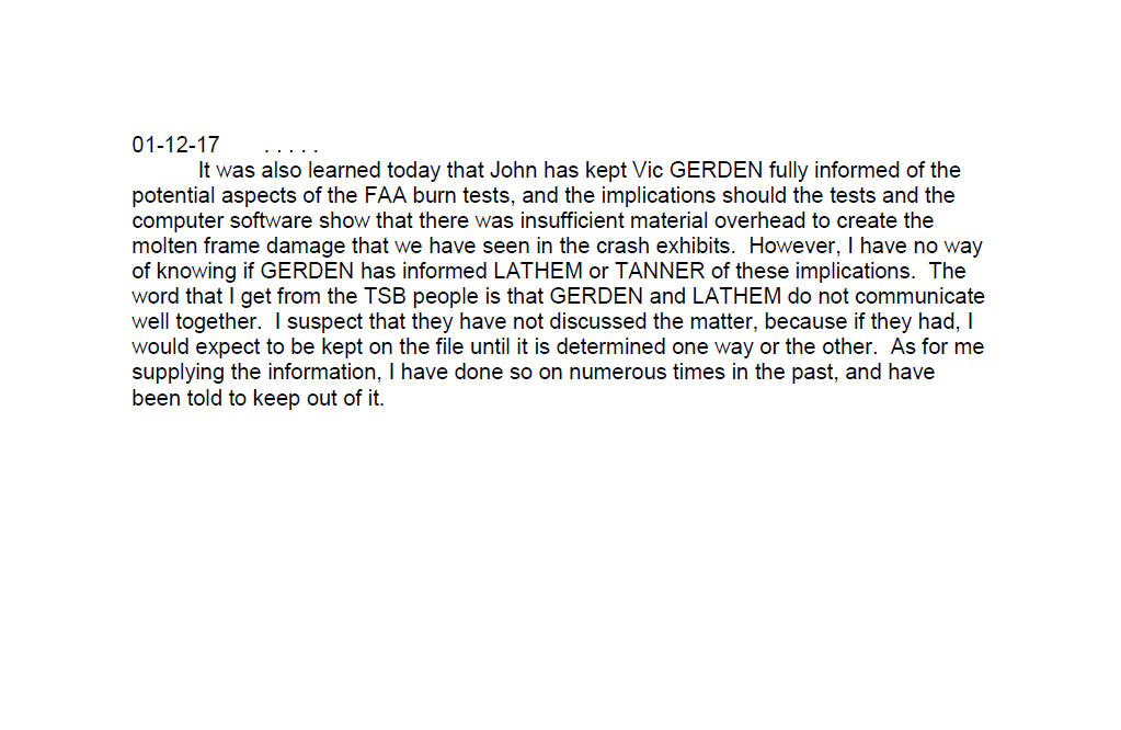
Gerden most certainly had control of the burn tests.
After all, he had to account for the expenses not only of his own investigation
and his investigators,
but also the time and effort and the associated cost put forward
by the people at the FAA burn centre.
In addition,
he had to request my time from the RCMP.
As for Lathem,
I doubt that he cared.
He was simply following orders
that had come down from the Commissioner's office in Ottawa.
The following is taken from my file notes of the 'fraud' fire.
At about 1645 hrs, with everything set up (my two cameras and the two FAA cameras),
we ran the MPET bulk burn test.
To say the least, it was spectacular.
With the tapes rolling,
it was started in the normal manner after three electronic flashes,
and Don ENNS set alight the material from underneath.
Very quickly it caught,
the frame filled with smoke,
and nothing more could then be seen.
The frame belched thick black smoke from every crack and hole,
the smoke stack billowed smoke like a locomotive burning coal,
and everything snapped and popped from the high heat.
Part way into the fire,
the upper surface of the frame caught fire and was put out with a garden hose and a fine spray.
Because nothing could be seen through any of the viewing ports or openings,
the cameras were all pulled back – for the safety of the equipment
as I didn’t know if the frame would sustain the fire.
The building filled with smoke,
and the viewing port glass on the left side broke from the heat and flexing of the tin frame.
Eventually the centre ceiling panel fell partly to the floor
and it could be seen that most of the material was already burnt.
It would appear that the tin gave way as it cooled back to room temperature and shrunk.
Photos during the actual burning were taken on roll #037.
On completion of the burning,
the frame ends were removed and I took a series of panoramas on roll #038, position A & B.
In taking the pans,
initially the insulation was still in the ceiling of the frame.
In position A,
one piece was hanging down in such a manner as to totally block the camera.
So I cut it off at the frame level to allow a complete view of the frame.
Because of the amount of damage to the frame created by the fire,
it was decided to allow the frame to cool down completely
before conducting a further post-fire examination.
This video link shows the footage again taken from two cameras,
one positioned at each end of the burning frame.
The videos are synchronized and shown in screens one beside the other,
and they are edited
to eliminate unnecessary lead times at the beginning of each and the post-fire frame examination.
One can note the amount of Metalized Mylar,
the way it is positioned,
the rate of burn
and the short time it takes before the frame fills with smoke so that nothing can be seen.
The high heat being generated can be gauged by the fact that the Mylar tends to move
and shrink away from the flame during the initial fire stages.
As shown, the smoke generated was tremendous.
However, even though at times there is little to see,
keep listening as the snapping and popping noises that are made are from the frame expanding
due to the extremely high heat.
The broken viewing port shown at the end of the video had been made of heat-resistant safety glass.
| -- FAA-3 MYLAR FRAUD BURN TEST VIDEO -- |
| ------------ SITE MAP ------------ |
* * * * * * * * * * * *
FAA BURN TEST FRAME DISPLAY
|
Burn Test Results |
||||||
|
|
MATERIAL BURNT |
FOURTH DUCT PRESENT |
# OF TIMES IGNITED |
ALL OF FIRE-LOAD CONSUMED |
ALUMINIUM MELTED |
OTHER |
|
FAA2 Phase 1 |
AN-34 |
YES |
SEVERAL |
NO |
NO |
FIRE TEST COMPLETE FAILURE |
|
FAA3 Phase 1 |
INSULFAB 350* |
YES |
SEVERAL |
NO |
NO |
FAILED TO BURN CEILING AREA |
|
FAA3 Phase 2 |
INSULFAB 350* |
YES |
SEVERAL |
NO |
NO |
HEATER UNIT PREHEATED FOURTH DUCT |
|
FAA3 Fraud Test |
INSULFAB 350* |
NO |
ONE |
YES |
YES |
SIX TIMES NORMAL FIRE-LOAD |
* INSULFAB 350 IS THE METALIZED MYLAR COVERING FOR THE CEILING INSULATION BLANKETS FROM HB-IWF (VAUD)
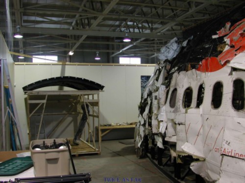
The FAA test frame was sent to Halifax via Ottawa to end up on display beside the main reconstruction jig for the aircraft. As one walked in the door to the secure room in the hangar, the frame was on a six-foot stand in the far left corner beside the nose area of the reconstructed jig.
As one moved about looking at the reconstruction jig, the damage to the FAA frame could easily be viewed. However, by this time I was on my last days in the hangar and soon there would be no one left to explain the nature of the fire that had caused this amount of damage to the FAA frame.
What is interesting is that the damage caused to the FAA frame is similar in nature to that found in the reconstruction jig. Both have been through an exceptionally hot fire that melted parts of the frame structure. While the FAA frame received a crack in the skin material, HB-IWF did not. That was because the skin was so cold. However, with this thought of similar damage in mind, remember that the FAA frame burnt with six times the amount of Metalized Mylar material in less than one-quarter of the time as did the fire on HB-IWF, but without a cold-sink and with abundant supplies of oxygen.
Now, the argument might be presented that these FAA burn tests were not designed to replicate the fire on HB-IWF.
Without conducting an actual fire during a flight test, such a replication would be nearly impossible to do.
However, regardless of what the intentions were for the fire tests
Metalized Mylar, when exposed to flame, burnt and caused a fire front to travel along its length.
However, it did not erupt into a raging inferno when it was set alight under normal fire conditions.
When in single layers with fibreglass insulation between those layers,
it failed to burn at anything but a slow rate
with only a minimum of heat generation.
It was only when the MPET material was burnt in a totally artificial manner
by being crumpled up with excessive amounts of Mylar material mixed with air
did it create what can only be called an immediate and extreme inferno or firestorm.
This is something that did not happen in this manner during the flight.
However, if the FAA burn tests were not designed to attempt to replicate conditions on HB-IWF
and if the fire test results were not considered as representing the fatal fire results
why then did the TSB rent a truck to haul the burnt and melted frame all the way back to Ottawa?
Then, why ship it by commercial freight to Halifax
to have it put on display beside the reconstruction frame of the forward burnt section of HB-IWF
for all to see and compare?
| ------------ SITE MAP ------------ |
| ----------- TimE line ----------- |
* * * * * * * * * * * *
FAA BURN TEST MATERIALS
During the burn tests held at the FAA in the fall of 2001,
the mock frame had three ducts installed to represent the three main ducts that ran over the top of the galley ceiling.
They originated as the Queen Mary Ducts which came up out of the floor area just ahead of the right forward or 2.1 door.
For the fire tests, the ducts were wrapped in Metalized Mylar,
material that formed part of Dr. Lyon's estimate of 1000 gms or 2.2 lbs of Metalized Mylar.
However, an examination of the photos taken onboard numerous Swissair aircraft indicated something different.
Only HB-IWA had the three main ducts wrapped in Metalized Mylar.
One other plane had two of the three similarly wrapped.
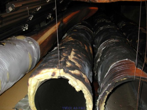
This photo shows the ducts of HB-IWA as viewed through the ceiling hatch just behind the flight deck door. The shiny Metalized Mylar is on all the ducts. In the upper left quarter of the opening are two large curved ducts that are two of the three main ducts. The top of the photo is the right side of the aircraft. Similar photos as shown were taken on HB-IWB, HB-IWC, HB-IWE, HB-IWI, and HB-IWM. Except on HB-IWC, they all indicate that the ducts were wrapped in the dull coloured Metalized Tedlar. On HB-IWC, only two of the three were wrapped in Metalized Mylar.
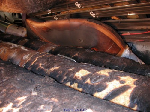
The forward area of two aircraft, HB-IWU and HB-IWN, were thoroughly examined when in 'D' check. The photos show that Metalized Mylar did not wrap the ducts. This photo shows the three main ducts of HB-IWU, as seen from the underside with the ceiling frame and light in the same position as the previous photo. The bend in the ducts shown in the above view can be seen on the right of this photo. The light in the ceiling bar that runs from top to bottom at the mid-right area of the photo is part of the ceiling hatch just aft of the flight deck door. So as one stands midway between the two forward doors and looks up through the ceiling, one would see the ducts like this, wrapped in Metalized Tedlar.
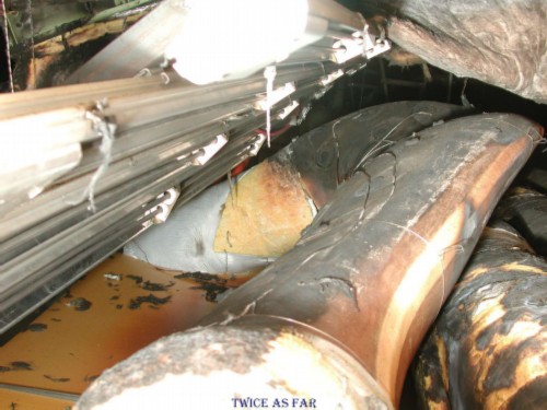
HB-IWE was considered the closest sister ship of HB-IWF as both were received by Swissair at the same time as new aircraft. HB-IWE was flown for the Long Beach airflow test because it most closely matched Vaud in equipment and age. This photo shows the fourth duct just below centre on the right of the photo with the left forward door in a raised position above it. Below the fourth duct can be seen the three main ducts with their insulating wrap. In the upper half of the photo, the shiny Metalized Mylar can be seen covering the insulation blankets of the skin and frame pieces. There is a difference in the colouring of the skin's Metalized Mylar and the material around the ducts thus indicating that they are not the same material. This photo was taken during the Long Beach airflow tests, so cables and metal bars have been added to allow for the test's cameras and lights.
If only the older aircraft in the fleet, HB-IWA and HB-IWC contained the flammable Metalized Mylar as duct wrap, and the others had Metalized Tedlar to perform that function, why then conduct the burn test with Metalized Mylar? With the much less flammable Metalized Tedlar added to the ducts it would have reduced the estimated fire load by at least 20%. Instead of one kilogram, there would have been 800 grams of Metalized Mylar for the burn, or about two pounds. However, even the incorrect amount failed to melt aluminium.
So in fact the 'fraud test' utilized more than six times the amount of flammable Metalized Mylar material as was present in the area on HB-IWF.
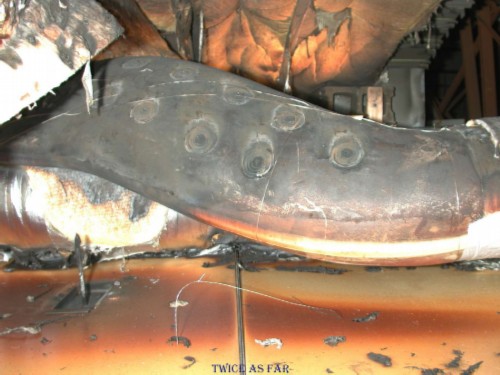
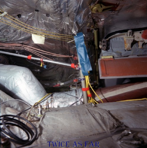
This photo was taken looking forward on the right side of HB-IWE during the preparations for the Long Beach airflow test. In the mid-lower left of the photo can be seen some of the power cables added for the airflow equipment including the orange and yellow extension cables. To the lower right of centre can be seen the waterfalls area where the wires drop down to pass under the right forward 2.1 door when it is raised, and the black metal sloped door ramp can be seen in the lower right quarter of the photo. Where those wires in this photo dip down and pass towards the rear of the aircraft at a level just above the galley ceiling, they are covered by a shroud that is in the lower left area of the photo, the large grey curved shield-like object. While this piece of equipment was supposed to have been removed from the aircraft, not all of the Swissair aircraft had been through that removal process. There is every reason to believe that Vaud may have had such a shroud still in place as there was no confirmed record of it ever having been removed. Such an object on Vaud would have protected the wiring beneath it if a fire had started on or above the right forward ceiling tiles at the door area. With an added accelerant, it too would be consumed. However, its presence may have delayed any damage to the wires until the fire had spread to encroach the flight deck area.
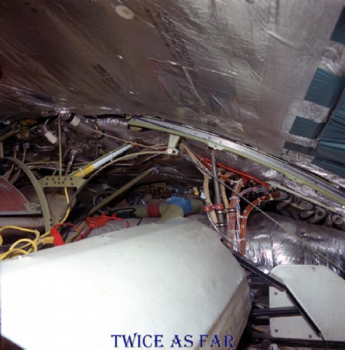
This photo also shows the conduit or tubes through which the wires are encased allowing them to pass between this area and the fuse panels on the flight deck. They are located just below the ceiling on the right or just below the right middle of the photo, to the right of the waterfalls wires. It can be seen clearly that they are not capped to block air (or smoke) from being sucked forward to the flight deck area by the air flow system. This likely corresponds to the condition of those same conduit tubes that were on HB-IWF. Now remember that it took ten minutes from the time of smelling the smoke until failures were recorded on the flight data recorder. A fire on the ceiling surface and this shroud at the right forward door might take that long to burn through to the wires. The smoke would be sucked through the tubes by the flight deck air circulation system. This would also account for the lengthy and intense burn on the door area ceiling tiles that are just outside of this photo's view. As for the shiny Mylar material seen above the shield and below the cable conduits, during the Zurich III trip the Boeing people advised that the wrap in that location was the non-flammable AN-34 Mylar, the same material that was mistakenly used in the first FAA burn test and that failed to burn. However, given sufficient heat provided by an accelerant, that Mylar and the green material overhead the door might burn and thus add to the fire load. This would account for the fact that none of that material was ever recovered.
| ------------ SITE MAP ------------ |
| ----------- TimE line ----------- |
* * * * * * * * * * * *
NOTES OF EMAIL FROM DON ENNS
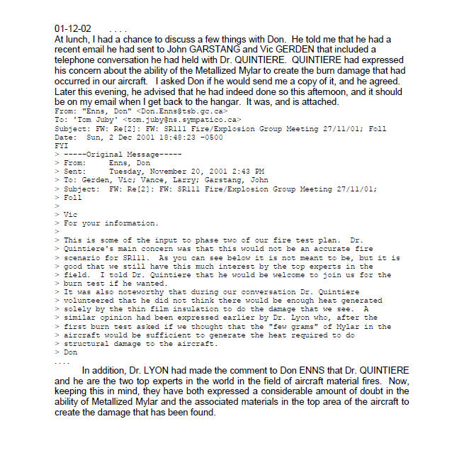
There is more to this email,
but it includes emails from Garstang explaining the reason for this fourth duct burn test
and why it was done in this manner.
However, the important part is shown here in the second paragraph of the email.
At this stage, how and why the tests were designed is irrelevant.
No matter what was done,
no aluminium melted until the last burn test was conducted.
However, both Dr. Lyon and Dr. Quintiere
have expressed doubt about the ability of the fire load to do the damage that was done.
Who in the RCMP or the TSB had the qualifications to counter their opinions?
* * * * * * * * * * * *
| ------------ NEXT PAGE ------------ |
| -------------- SITE MAP ------------- |
| ------------- TimE line ------------- |
| ------------ Home Page ------------ |
![]()
![]()
![]()
![]()