
_svg.png)
TWICE AS FAR

SWISSAIR 111
CRASH INVESTIGATION
![]()
![]()
![]()
- EXTRACT FROM FILE NOTES -
FOR
- 2001 DEC 01 -
FAA-3 PHASE 1 METALIZED MYLAR BURN TEST
A repeat of the FAA-2 phase 1 burn test was held as the first burn of the FAA-3 trip,
only this time, Metalized Mylar of the type believed to have been on HB-IWF, Insulfab 350, was utilized.
What is disturbing is that during these tests,
the main ducts were wrapped in Metalized Mylar Insulfab 350.
A closer review of the aircraft inspection photos showed that on all but two of the examined aircraft
the same ducts appeared to have been wrapped in the non-flammable Metalized Tedlar
or a material other than the flammable Insulfab 350 Metalized Mylar.
At the time of the inspections, I had noticed but didn't appreciate the difference.
However, only by reviewing the aircraft photos for these pages has that discrepancy now been realized.
The overhead exterior skin insulation was indeed covered in the flammable Metalized Mylar,
but not these main air-handling ducts that ran through the area.
The following is taken from my notes of the FAA burn test.
The fire in the frame was started in the same manner as in the FAA-2 test.
The electronic flash was fired three times at five-second intervals with all the tapes running,
the third being the start point for the counter.
Don then lit the Metalized Mylar from below and it was noted to readily burn.
A large amount of smoke was created and photos were taken of it on roll #004.
It was noted that smoke in the building came down to a level of about nine feet above the floor.
In total, about half of the Metalized Mylar on the three ducts burnt,
but nothing in the ceiling was damaged,
and it appears that no damage was done to the foam duct.
These photos show the setup and the results
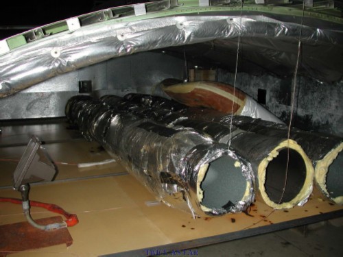
The frame setup was the same as during the first attempt to burn the material, only this time flammable Insulfab 350 Metalized Mylar was applied to the ducts. The ceiling has the same material.
Once the burn was over, this photo shows the extent of the damage in the area of the fourth duct. There was no damage to the top of the duct and little to the material directly below it. The Mylar on the bottom of the main duct is burnt away, but it is noteworthy that the flame front did not continue its natural progression up and along the side of the duct. By this photo, one might think that the Metalized Mylar could indeed pass a legitimate fire test.
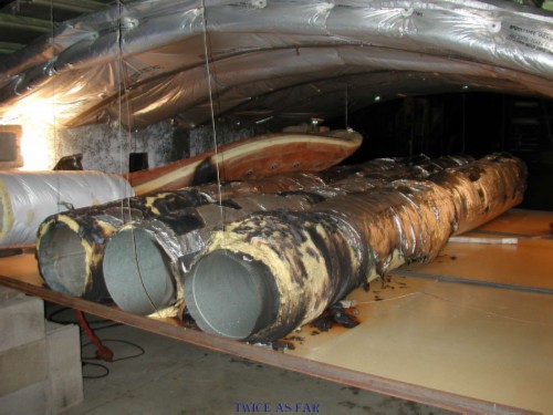
This view hows the overall area of the frame floor and how much of the Metalized Mylar remains on the ducts. The ceiling blankets are untouched. Their actual height above the ducts corresponds to that in the MD 11 aircraft at this point in the fuselage. One can see an area of blackening on the fourth duct just left of photo centre.
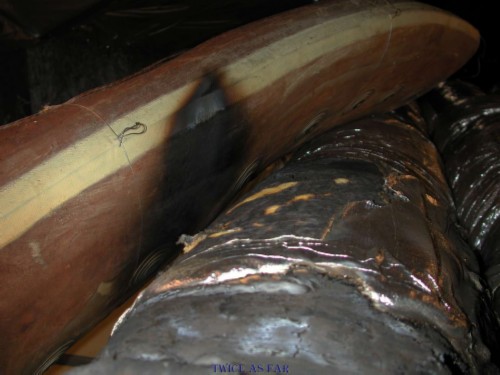
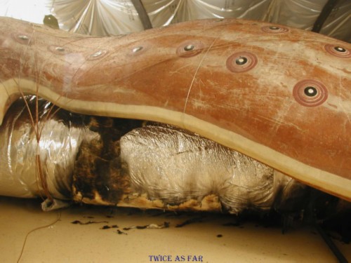
This photo shows the extent of the damage to the fourth duct. While it may give the impression of having been burnt, it is mainly soot from the burning Metalized Mylar that was on the underside of the duct
Once phase 1 was completed,
preparations were undertaken to conduct the phase 2 burn test
to determine if the fourth duct would burn.
It was important to determine if it added to the fire load in the overhead area.
The theory for the test was that
because the fire had likely started on the right side or the side of the aircraft opposite the fourth duct,
this duct would have been pre-heated by the hot gasses before flames ever reached it.
Therefore a high output heating unit was installed to perform that task.
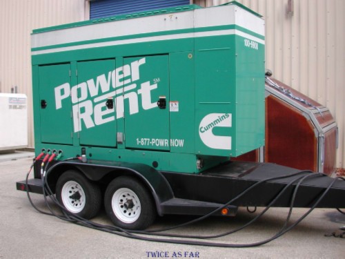
This photo shows the generator that was required to run the heater units that were placed in the frame for the FAA-3 phase-2 burn test. The FAA facility provided 208 V electrical power while the heaters required 240 V power.
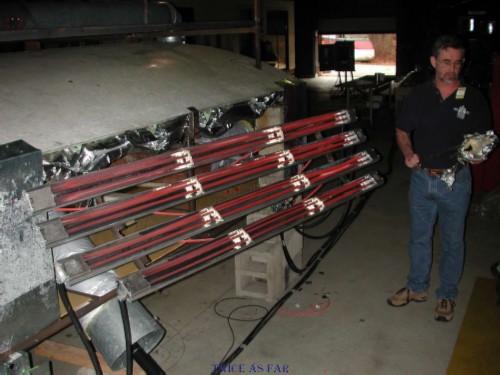
This photo shows the heater units being tested outside of the frame with Don Enns standing beside them. However, he didn't stand there for long before it became too hot. With the correct voltage, the output was tremendous, as can be seen in the video that follows.
The dimensions of the heater panels are as follows:
Length of the three long panels: 85.5 in
Length of the one shorter panel: 73 in
Width of each panel: 3 5/8 in
Overall width of the panels, top to bottom: 20 in
The heat output was not recorded in my notes.
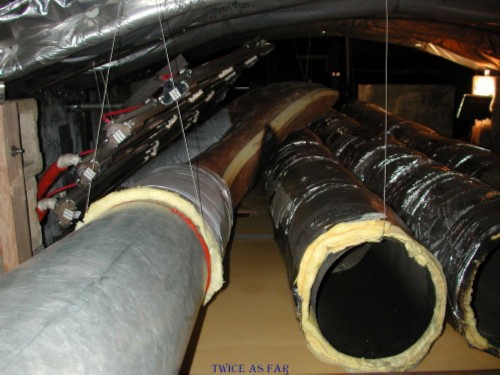
This photo shows the setup with the three main ducts in place and freshly wrapped in the Insulfab 350 Metalized Mylar with the fourth duct to the fifth zone to the left. The ends of it are wrapped in Metalized Tedlar, and the difference is obvious. The electric heaters have been positioned atop the fourth duct. The theory behind it was that the fire likely first occurred on the right side of the ceiling area and it produced sufficient heat to preheat the fourth duct before it caught fire. In this test, the heater units served to preheat the duct.
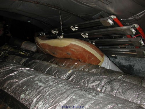
This photo shows the frame setup from the opposite end, or what would be looking towards the rear of the aircraft from ahead of the galley area. The difference here compared to the aircraft was that the three Metalized Mylar covered ducts in the aircraft would have originated in the lower left corner/middle of the photo and then they would immediately turn left to travel towards the rear of the frame.
In this photo it is shown just how much heat can be applied to the fourth duct. Above the duct are the heater units. Below it is the flammable Metalized Mylar that burns with a flame front of about 2200 deg F. However, the question was whether or not the Metalized Mylar was sufficient to provide enough heat to ignite and burn the duct and the Metalized Mylar in the ceiling. Dr. Lyon of the FAA suggested that the overall weight of Metalized Mylar present in this area of the aircraft did not exceed 1 kg or 2.2 lbs. His estimate included the Metalized Mylar on the three main ducts.
The following is taken from my notes for the results of the fire:
Generally, the burn went very well, with the foam duct smoking and then burning while the heaters were activated.
However, as soon as the heaters were turned off, the foam duct quickly extinguished itself.
Just before shutdown, one of the heater units shorted out and sparks were sent flying about the frame.
It appears that one of the sparks landed on an area of the horizontal ducts and caused the Metalized Mylar to catch fire.
The material caught fire and burnt for a period of time,
having been caught on the digital video footage from the left forward corner of the frame.
However, all of the Metalized Mylar in the frame did not burn,
and holes had to be drilled in the walls to allow fire initiation of the ceiling inter-blanket material.
* * * * * * * * * * * *
| ------------ TIME LINE ------------ |
![]()
![]()
![]()
![]()