
_svg.png)
TWICE AS FAR
SWISSAIR 111
CRASH INVESTIGATION
![]()
![]()
![]()
- EXTRACT FROM FILE NOTES -
FOR
- 1999 OCT 16 -
THE THIRD ZURICH TRIP
INSULATION BLANKET REMOVAL
By the time of this crash, the airline industry had already been told to remove the Metalized Mylar that covered many of the Boeing aircraft's insulation blankets. The material had been found to be very flammable at normal fire temperatures. The question raised by John Garstang was whether or not the replacement material was just as flammable in an environment of short-circuiting wires. Was one problem being replaced with yet another?
It was decided that the insulation blankets removed from the Swissair aircraft would be collected for a later series of burn tests. At the same time, photos of the equipment and bare aircraft could also assist in the investigation.
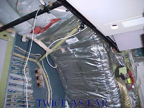
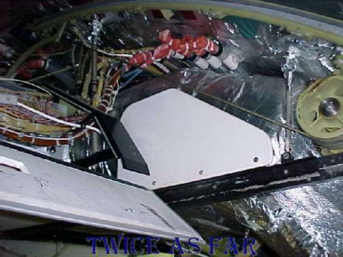
This photo shows an area of three ducts that are called the Queen Mary ducts. They are located just ahead of the right forward 2.1 door and are a major part of the air circulation system in the aircraft. This photo shows that the ducts are wrapped in an insulation material, the photo having been taken after the removal of the right forward galley unit. The three separate ducts can be seen in the top left corner wrapped in the grey Metalized Tedlar insulation. Then an outer wrap of shiny insulation material can be seen in the lower area. The Boeing people who were present for the blanket removal process quickly realized that this outer wrap was not the same Metalized Mylar that had to be removed, but it was made of another series of Mylar that was much more flame resistant. Later tests showed that it would not maintain a flame front that would enable it to burn under normal conditions.
This photo shows the bottom area of the Queen Mary ducts and the right forward 2.1 door. The wall on the photo's left is the back side of the aft cockpit wall. On the other side of that wall is a fuse panel.
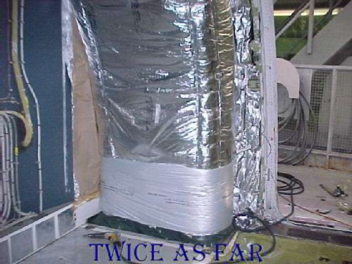
The area shown at the bottom of this photo is the top of the door frame for the right forward or 2.1 doorway to the aircraft. Looking through the door, the viewer can see a metal staircase and railing of the working area just outside of the aircraft. This forward door is of the type that raises and lowers on two tracks with a cable attached to a motorised drum system on each side. The door, now removed, rolls in the two metal tracks of which the forward track can be seen as the green painted strip of metal from a quarter of the way up the left side of the photo to the top left corner. The white and black horizontal material foremost at the photo's centre is a piece of ceiling frame that guides the flow of wires from the forward fuse panels on the left towards the rear of the aircraft to the right. To the left side of the photo and below the horizontal black and white ceiling piece can be seen one of the drums that turn to operate the door cable and thus lift and lower the door. A sheet of thicker blue-green rubberized-like material is positioned to cover and protect the relatively fragile material in the doorway's overhead ceiling area. This cover is present on both sides of the aircraft at the two forward doors. Later burn tests of this material proved that it was non-flammable at normal fire temperatures. The track on the left is the same track that on HB-IWF was found to have suffered extremely high heat thus causing it to bend and part of it to melt.
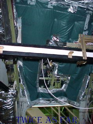
This photo shows the edge of the Queen Mary ducts beginning at the photos right
of centre and heading into the photo's
centre. This view is from the door opening in the previous two photos.
The wheel and cable system, one of which is visible
on the right side of the
photo, is the mechanism that raises and
lowers the door. The door track can be seen going across the top of the
photo and is the location for the debris
track that was found to be bent and twisted due to the extremely high heat as
well as having the 'broom straw' molten metal. Just left and above centre
is the electrical cable run position
called the ‘waterfalls.' The wires
come out of the tubes that can be seen capped with
a reddish-orange wrap and they drop down
to the piece of ceiling frame that guides and protects their route towards the
rear of the aircraft located back over the viewer's left shoulder. The
black metal strip left of photo centre and angling up to the left is the door
deflector that is in a position to guide
the door flap as it raises/lowers and to ensure that it does not interfere with
the electrical cables. One of the concerns was the possible contact
between the door cable and the electrical wires since the cable moves up and
down to raise the door. No evidence of contact
was seen on any of the MD-11's that
were examined.
The space through which the area
is now seen
is usually covered by a piece of ceiling tile.
Its
thickness at these two forward doorways is unique within the
aircraft, and thus a piece of it can
be positioned at either of the two forward
doorways. Two small pieces of this thin
material were found to have burnt extensively.
The estimate was that the tiles had burnt for five minutes at 1700 deg F or ten
minutes at 1100 deg F. Considering the non-flammability of the adjacent
Mylar material of the Queen Mary ducts, the ceiling cover in this area, and the
lack of any other substantial fire load in this immediate vicinity, one has to
question what was burning for so long at such a hot temperature.
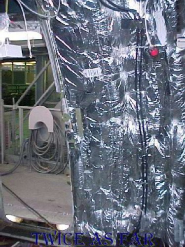
This photo shows the right side of the same doorway 2.1, or the right forward door of the aircraft. Metalized Mylar covered the main insulation blankets that were behind the right forward first class lavatory and that are still in place. These blankets have been tagged with their exhibit numbers, one being visible as the white tag with the 1-11311 marked on it.
The exhibit numbering system set up for the aircraft reconstruction hangar was simple. Aircraft related exhibits belonged in the 1- series beginning at 1-1 and going all the way to 1-11311 as shown here. In total there were more than 18,000 numbered exhibits. Whenever one exhibit was divided for a purpose such as a burn test or other analysis, the original retained the initial exhibit number while the new piece was given the next available sequential number. So if a sample was later taken from this blanket 1-11311, the next number available might have been 1-15000. To simplify things even more, if an item was constructed out of numerous previously numbered exhibits, - sometimes as many as one hundred or more exhibits - it was given a new single exhibit number. All the other exhibit numbers were added to its description in the computer.
The morgue numbering system, set up by Insp. Lee Fraser was entirely different and too convoluted even to describe here other than to say it utilized groups of both letters and numbers in various sequences depending on its stage of processing. There is always need to keep these systems simple. Too many problems can occur when mistakes are made while transcribing complicated numbering systems after long tedious hours of work. The morgue system showed just how little experience Lee had when it came to major file investigations. Today, I hope that a computerized barcode system would be utilized that would simplify the recording process.
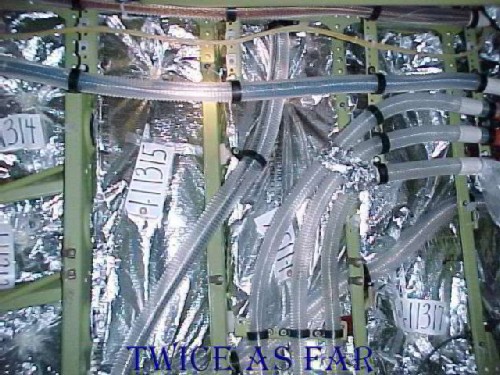
Once the main blanket covering is removed, what remains are the individual smaller blankets that fit between the ribs of the aircraft, or stringer in Boeing terms and longeron in Swissair jargon. Here the main covering has been removed, and the smaller pieces are marked with exhibit tags. The blankets are simply two layers of Metalized Mylar material sealed on all four sides to encase a fibreglass insulation bat. The only actual difference is the size. So in effect, there is a double layer of fibreglass insulation with four layers of Metalized Mylar.
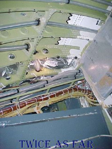
Once everything is removed there remains the painted inside surface of the aircraft skin. In this instance, some of the skin has been painted white, and two blankets are still in place. During initial construction, the insulation blankets are installed first, and then the wire runs pass through holes created in the blankets. The insulation bats must be sealed to eliminate the absorption of water during the flight. Water absorption would drastically reduce its insulation value and add considerable weight to the aircraft besides causing mould. Information from Swissair revealed that during a normal flight as much as 500 kg or litres of condensed water is retained on the overhead material surfaces. Also in this photo one can see a bundled wire run, and how the white nylon ties are closely spaced to maintain the bundle's integrity.
* * * * * * * * * * * *
| ------------ time line ------------ |
![]()
![]()
![]()
![]()